Electrical
16 Design Guide
1. For example, for a rated +5 VDC output of 14A, the transient step would be
30% x 14 A = 4.2 A.
2. The numbers are based on the 10
th
gen Intel
®
Core
TM
Desktop CPU family, subject to
change. Contact the Intel
®
representative for the up to date CPU electrical specification
max step size of the CPUs that will be assembled for system integration.
3. 12V3/V4 rails are typically used for PCI-E Graphic card connectors. Some power supplies
use one large 12V rail or other configurations. This recommendation comes from
Graphics card recommendations and should be applied to the amount of current of the
12V rails associated with the graphic card connections. This is not an Intel
®
requirement
and so it will be treated as a recommendation during testing.
Output voltages should remain within the regulation limits of Table 3-2, for
instantaneous changes in load as specified in Table 3-3 and for the following
conditions:
• Simultaneous load steps on the +12 VDC, +5 VDC, and +3.3 VDC outputs (all
steps occurring in the same direction).
• Load-changing repetition rate of 50 Hz to 10 kHz
• AC input range per Section 2.1 and Capacitive loading per Table 3-6
.
3.2.3 Remote Sensing - Recommended
Remote sensing is recommended. Remote sensing can accurately control motherboard
loads by adding it to the PSU connector. The +3.3 VDC output should have provisions
for remote sensing to compensate for excessive cable drops. In low power PSU, remote
sensing is recommended. The default sense should be connected to pin 13 of the main
power connector. The power supply should draw no more than 10 mA through the
remote sense line to keep DC offset voltages to a minimum.
3.2.4 Other Low Power System Requirements - Recommended
To help meet the Blue Angel* system requirements, RAL-UZ 78, US Presidential
executive order 13221, ENERGY STAR*, ErP Lot6 requirements, and other low Power
system demands, it is recommended that the +5VSB standby supply power
consumption should be as low as possible. In order to meet the 2010 and 2013 ErP Lot
6 requirements, 2014 ErP Lot 3 requirements, and if any Computers use an Alternative
Sleep Mode (ASM) then the 5V standby efficiency should be met as shown in Table 3-4
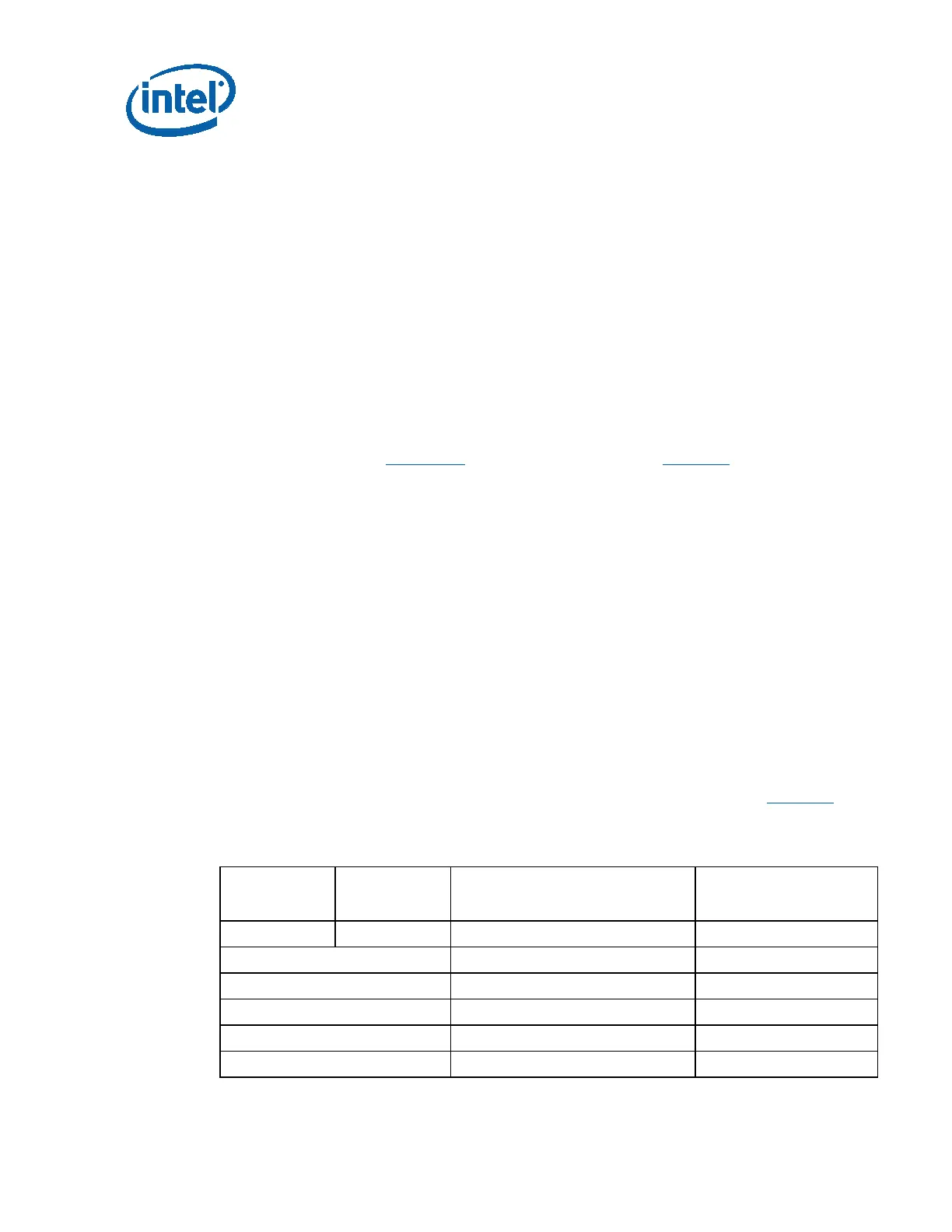
which is measured with the main outputs off (PS_ON# high state).
Table 3-4: Recommended System DC and AC Power Consumption
5VSB
Load Target
5VSB
Actual Load
Efficiency Target
(Both 115V and 230V Input)
Remark
Max / Label 3.0A / Label 75% Recommend
1.5 A 75% ALPM and ErP Lot 3 2014
1.00 A 75% Recommend
0.55 A 75% ALPM and ErP Lot 3 2014
90 mA 55% Recommend
45 mA 45% ErP Lot 6 2013