Mechanical
32 Design Guide
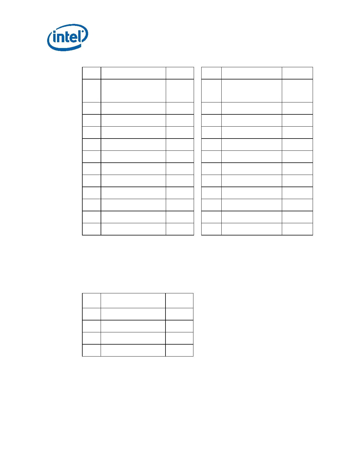
Table 4-1: Main Power Connector Pin-Out
Pin Signal Color Pin Signal Color
1
+3.3V DC Orange
13
+3.3V DC
[+3.3 V default
sense]
Orange
[Brown]
2
+3.3V DC Orange
14
-12V DC Blue
3
COM Black
15
COM Black
4
+5V DC Red
16
PS_ON# Green
5
COM Black
17
COM Black
6
+5V DC Red
18
COM Black
7
COM Black
19
COM Black
8
PWR_OK Gray
20
Reserved NC
9
+5VSB Purple
21
+5V DC Red
10
+12V1 DC Yellow
22
+5V DC Red
11
+12V1 DC Yellow
23
+5V DC Red
12
+3.3V DC Orange
24
COM Black
4.2.2.2 Peripheral Connectors
Connector: AMP* 1-480424-0 or Molex* 15-24-4048 or equivalent.
Contacts: AMP* 61314-1 or equivalent.
Table 4-2: Peripheral Connector Pin-Out
Pin Signal Color
1
1
+12V1 DC Yellow
2
COM Black
3
COM Black
4
+5 VDC Red
NOTE:
1
18 AWG wire.