Mechanical
Design Guide 33
4.2.2.3 Floppy Drive Connector – Do Not Include (For Historical
Reference Only)
Connector: AMP* 171822-4 or equivalent.
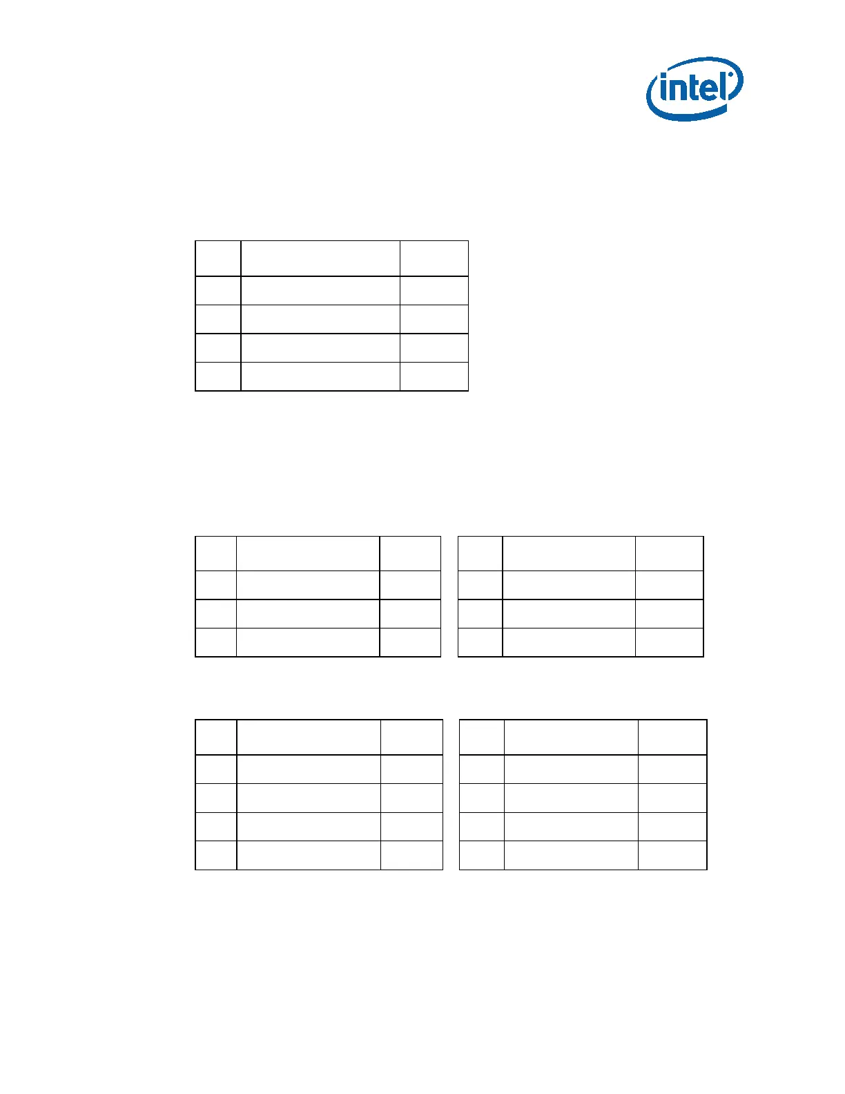
Table 4-3: Floppy Connector Pin-Out
Pin Signal Color
1
1
+5V DC Red
2
COM Black
3
COM Black
4
+12V1 DC Yellow
NOTE:
1
20 AWG wire.
4.2.2.4 PCI-Express* (PCIe*) Graphics Card Connector
This is an optional connector for the power supply to support additional power needed
by a discrete graphics card over 75 watts.
Table 4-4: PCIe* Graphics Card 6 Pin Connector Pin-Out
Pin Signal Color
1
Pin Signal Color
1
1
+12V3/V4 Yellow
4
COM Black
2
+12V3/V4 Yellow
5
COM Black
3
+12V3/V4 Yellow
6
COM Black
NOTE:
1
18 AWG wire.
Table 4-5: PCI-E Graphics Card 8 Pin (6+2) Connector Pin-Out
Pin Signal Color
1
Pin Signal Color
1
1
+12V3/V4 Yellow
5
COM Black
2
+12V3/V4 Yellow
6
COM Black
3
+12V3/V4 Yellow
7
COM Black
4
COM Black
8
COM Black
NOTE:
1
18 AWG wire.
4.2.2.5 +12 V Power Connector
Connector: Molex* 0039012040 or equivalent.