Mechanical
Design Guide 35
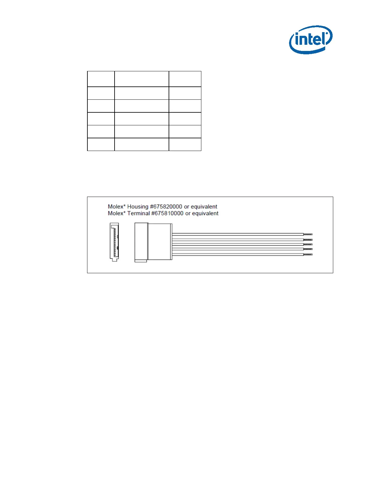
Table 4-8: Serial ATA* Power Connector Pin-Out
Wire Signal Color
1
5
+3.3V DC Orange
2
4
COM Black
3
+5V DC Red
2
COM Black
1
+12V1 DC Yellow
NOTES:
1. 18 AWG wire.
2. +3.3V DC is removed from SATA V3.2 specification. But it is recommended if there is
backward compatibility concern.
Figure 4-2: Serial ATA* Power Connector
4.3 Airflow and Fans - Recommended
The designer's choice of a power supply cooling solution depends in part on the
targeted end-use system application(s). At a minimum, the power supply design should
ensure its own reliable and safe operation.
4.3.1 Fan Location and Direction
In general, exhausting air from the system chassis enclosure via a power supply fan at
the rear panel is the preferred, most common, and most widely applicable system-level
airflow solution. However, some system/chassis designers may choose to use other
configurations to meet specific system cooling requirements.