Mechanical
34 Design Guide
Contact: Molex* 44476-1112 (HCS) or equivalent (Mating motherboard connector is
Molex* 39-29-9042 or equivalent).
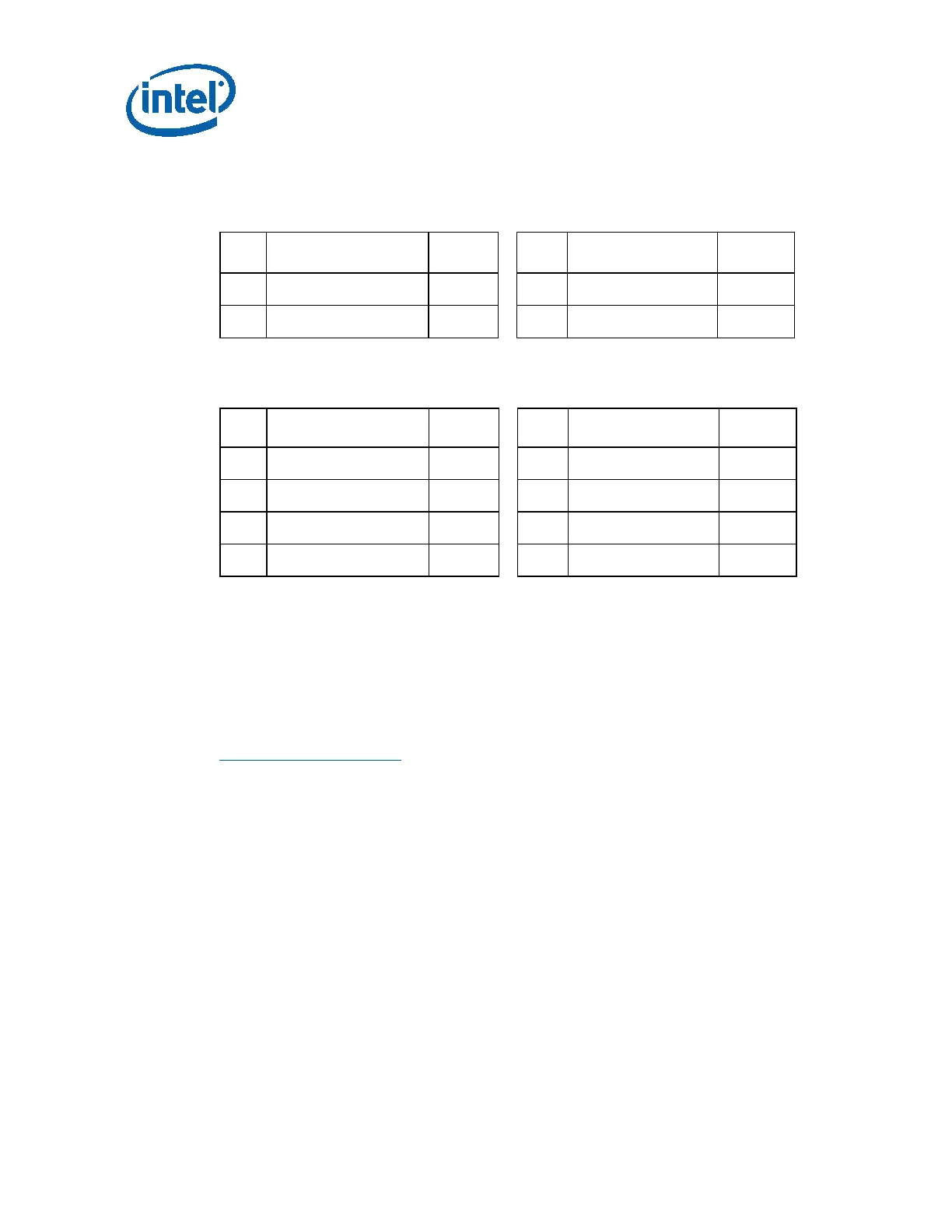
Table 4-6: +12 V Power 4 Pin Connector Pin-Out
Pin Signal Color
1
Pin Signal Color
1
1
COM Black
3
+12V2 DC Yellow
2
COM Black
4
+12V2 DC Yellow
NOTE:
1
18 AWG wire.
Table 4-7: +12 V Power 8 Pin Connector Pin-Out
Pin Signal Color
1
Pin Signal Color
1
1
COM Black
5
+12V2 DC Yellow
2
COM Black
6
+12V2 DC Yellow
3
COM Black
7
+12V2 DC Yellow
4
COM Black
8
+12V2 DC Yellow
NOTE:
1
18 AWG wire.
4.2.2.6 Serial ATA* Connectors – Required
This is a required connector for systems with Serial ATA devices.
The detailed requirements for the Serial ATA Power Connector can be found in the
“Serial ATA: High Speed Serialized AT Attachment” specification, Section 6.3 “Cables
and connector specification”.
http://www.serialata.org/
Note: Connector pin numbers and wire numbers are not 1:1. Carefully check to confirm the
correct arrangement.
Assembly: Molex* 88751 or equivalent.