Electrical
613768 31
NOTES:
12V2 rails are typically used for CPU power. CPU step size will have more updated
values in the Power Supply Design Guide Addendum (# 621484) which will be used to
determine the 85% value
12V3/V4 rails are typically used for PCIe* Add-in Card connectors. This
recommendation is based on Section
3 where PCIe* Add-in Card needs are discussed.
The step size will come from the amount of PCIe* Add-in Card power supported based
on the size of the PSU in Table 3-2
. For more detail reference the Desktop Platform
Form Factor Power Supply Test Plan (Doc # 338448)
If a power supply has multiple 12VHPWR connectors, Dynamic testing shall be done on
each 12VHPWR connector. For more detail reference the Desktop Platform Form Factor
Power Supply Test Plan (Doc #
338448)
Power supplies that have one combined 12V rail shall perform Dynamic testing on the
one 12V rail with multiple tests which simulate different system level workloads: 12V1
(total system), 12V2 (CPU Load), and 12V3/V4 (PCIe* AIC).
Output voltages should remain within the regulation limits of Table 4-2, for
instantaneous changes in load as specified in Table 4-3 and for the following
conditions:
• Simultaneous load steps on the +12 VDC output (all steps occurring in the same
direction)
• Load-changing repetition rate of 50 Hz to 10 kHz
• AC input range as per Section 2.1 and Capacitive loading per Table 4-7
.
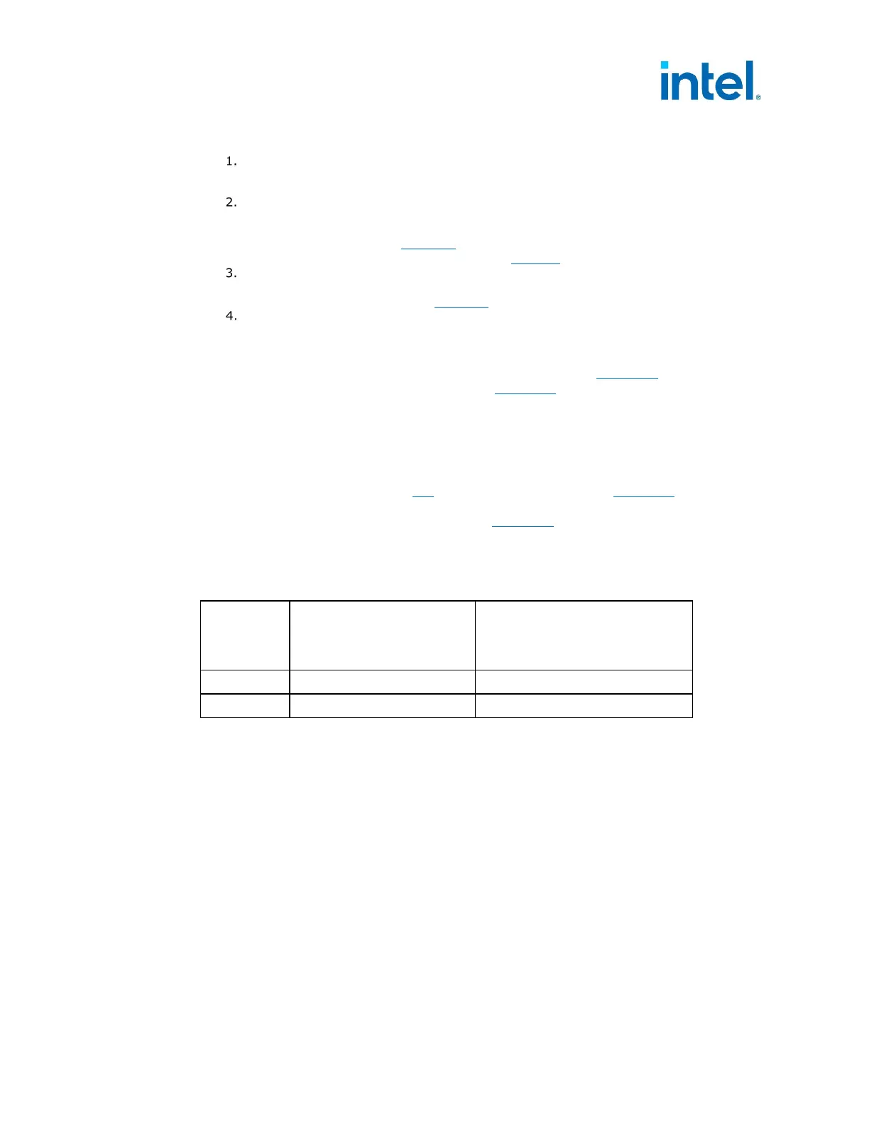
The transient load slew rate is defined in the Table 4-4 based on PSU supporting any
PCIe* Auxiliary Power Connectors. This usually can be correlated to the PSU’s Rated
Wattage, which is listed as a guidance.
Table 4-4: DC Output Transient Slew Rate
Output
PSU without PCIe*
12VHPWR Connectors
(Recommended Size
≤450 Watts)
PSU with PCIe*
12VHPWR Connector
(Recommended Size >450
Watts)
All +12V 2.5 A/µS 5.0 A/µS
+12VSB 0.1 A/µS 0.1 A/µS
4.2.3 Remote Sensing (Optional)
Remote sensing is optional. Remote sensing can accurately control motherboard loads
by adding it to the PSU connector. This is for the power supply to monitor the 12V
Voltage to the motherboard connector, through remote sensing, and then compensate
the voltage if there is excessive cable Voltage drop. The default sense should be
connected to pin 10 of the main power connector. The power supply should draw no
more than 10 mA through the remote sense line to keep DC offset voltages to a
minimum.
4.2.4 Other Low Power System Requirements (Required)
To help meet multiple world-wide Energy Regulations the +5VSB standby rail must
meet the following efficiency as shown in Table 4-5 which is measured with the main
outputs off (PS_ON# high state). These World-Wide Energy Regulations and standards