Mechanical
56 613768
The Sense pin on the 2x3 auxiliary power connector must be connected to ground
either directly in the power supply or via a jumper to an adjacent ground pin in the
connector. This pin is used by a PCI Express 2x3 150 W/225 W/300 W Add-in Card to
detect if the 2x3 auxiliary power connector is attached.
5.2.2.4.2 PCI Express* (PCIe*) 2x4 Auxiliary Power Connector
(Recommended)
The 2x4 Auxiliary Power Connector consists of a PCB_ Header, mounted on a PCIe*
Add-in Card, and a mating 2x4 Cable Plug harness. The 2x4 PCB header is designed to
accept both the mating 2x4 Cable Plug as well as the 2x3 cable plug, for
backward-compatibility. The Add-in Card PCB Header is keyed to ensure that a 2x3
cable plug from a PSU will be properly aligned when it is mated with a 2x4 PCB
Header. Two Sense pins in the 2x4 PCB header allow the PCIe* Add-in Cards to detect
the power available from the cable. The 2x4 Cable Plug asserts (grounds) two sense
pins to indicate that 150 watts are available to the PCIe* Add-in Card through this
cable, while the 2x3 plug asserts only one sense pin, to signal that only 75 W may be
drawn from the cable. The 2x4 Cable Plug has the following requirements:
• Current Rating: 7.0 A per pin/position maximum to a 30°C T-Rise above ambient
temperature conditions at +12 VDC with all eight contacts energized
• Mated Connector Retention: 30.00 N minimum when plug pulled axially
Cable Assembly Contact and Housing Details:
• Housing Material: Thermoplastic; Note that this connector has unique mechanical
keying to avoid wrongful insertion of cable plug meant for different types of
connectors.
• Pin Contact Base Material: Brass alloy or equivalent
• Pin Contact Plating: Sn alloy
• Flammability: UL94V-1 Minimum - Material certification or certificate of compliance
is required with each lot to satisfy the Underwriters Laboratories follow-up service
requirements.
• Lead Free Soldering: Connector must be compatible with lead free soldering process
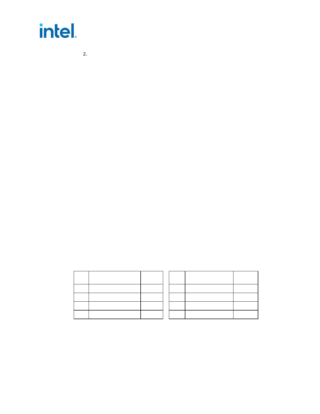
Table 5-8: PCIe* 2x4 Auxiliary Power Connector Pin Assignment (150 Watts)
Pin Signal Color
1
Pin Signal Color
1
1 +12V3/V4 Yellow 5 COM Black
2 +12V3/V4 Yellow 6 Sense0 Black
3 +12V3/V4 Yellow 7 COM Black
4 Sense1 Black 8 COM Black
NOTE:
1. 18 AWG wire.