Mechanical
613768 63
Table 5-13: SATA MB Power 4 Pin Connector Pinout
Pin# Volts Color
1
Max Amp Per
SATA HDD
Amp Per Conn Pin to Support
2 SATA Devices
1
GND Black 1.02 2.04
2
GND Black 2.5 5
3
12 Yellow 2.5 5
4
5 Red 1.02 2.04
The motherboard connection for this part does have 1 post that provides a mechanical
key for the connection next to the last circuit, just like the 6-pin connector does.
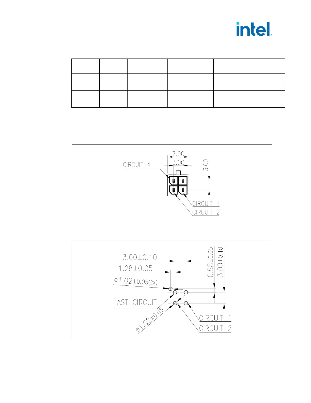
Figure 5-7: 3 mm SATA Power 4 Pin MB Header – Motherboard Connector Diagram (Pin
Locations and Latch Location)
Figure 5-8: 3 mm SATA Power 4 Pin MB Header – Recommended PCB Layout (Top Layer
View)
The 4-pin storage drive connector option recommended cable has two storage drive
connections over the length of the cable.