Electrical
613768 39
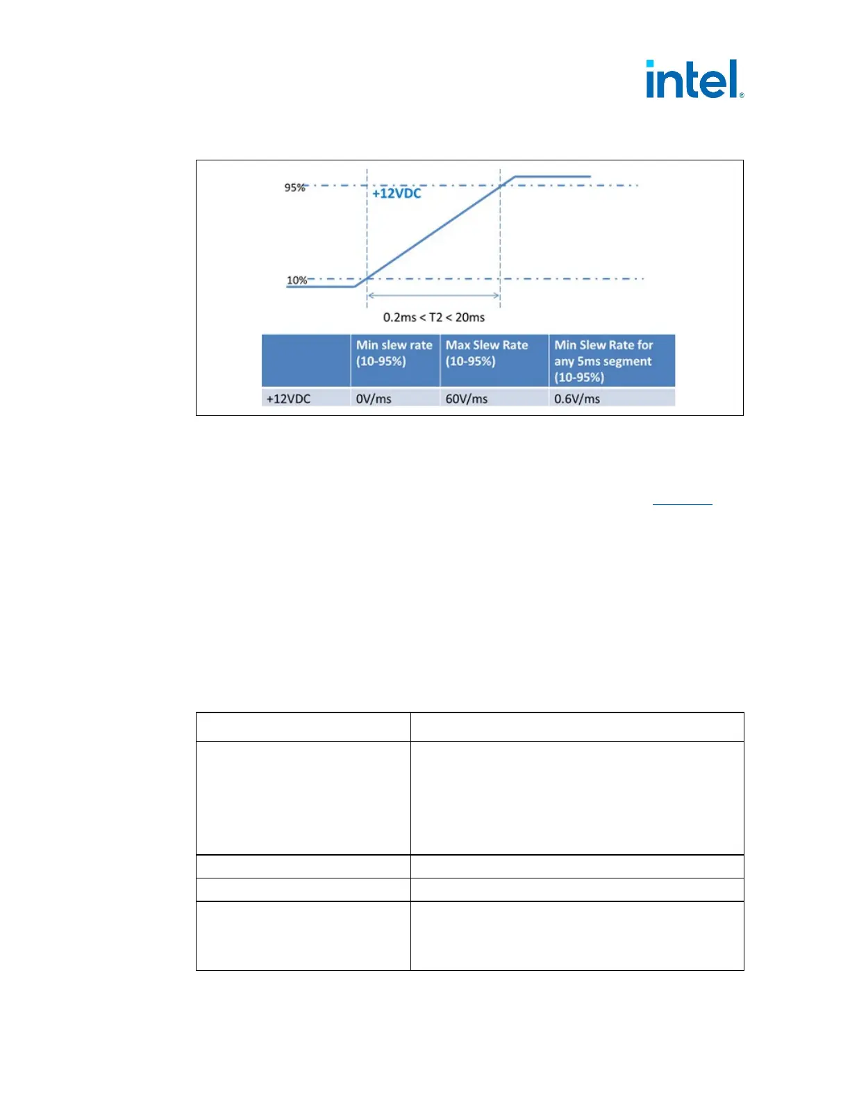
Figure 4-5: Rise Time Characteristics
4.3.6 Overshoot at Turn-On / Turn-Off (Required)
The output voltage overshoot upon the application or removal of the input voltage, or
the assertion/de-assertion of PS_ON#, under the conditions specified in Table 4-2
,
shall be less than 10% above the nominal voltage. No voltage of opposite polarity
shall be present on any output during turn-on or turn-off.
4.3.7 I_PSU% Signal (Required)
I_PSU% is a signal coming from the power supply that reports the proportionality of
Power being delivered by the +12VDC rail with the Output-Load rating of the PSU.
Which is represented as a unitless percentage of the total capacity using a current
mode. If multiple +12VDC rails are implemented (for example, +12V1DC, +12V2DC)
then I_PSU% must report the utilization ratio of the combined total capacity.
Table 4-11: I_PSU% Signal Characteristics
Parameter Description
Sensitivity
10 µA per 1% of capacity
1.0mA @ 100% of capacity
2.0mA @ 200% of capacity
Examples:
750W, 61A = 10uA /.61A
600W, 50A = 10uA/.5A
Maximum Reporting Capability 200%
1
Operational voltage range 0 - 3.3V
RL and CL Time Constant &
Sample Values
RC Time Constant Value = 924 ns = RL * CL
(± 10%, Error margin for RC Time Constant is large
due to variance in standard resistor and capacitor
values that would make up this time constant value.)