Mechanical
613768 53
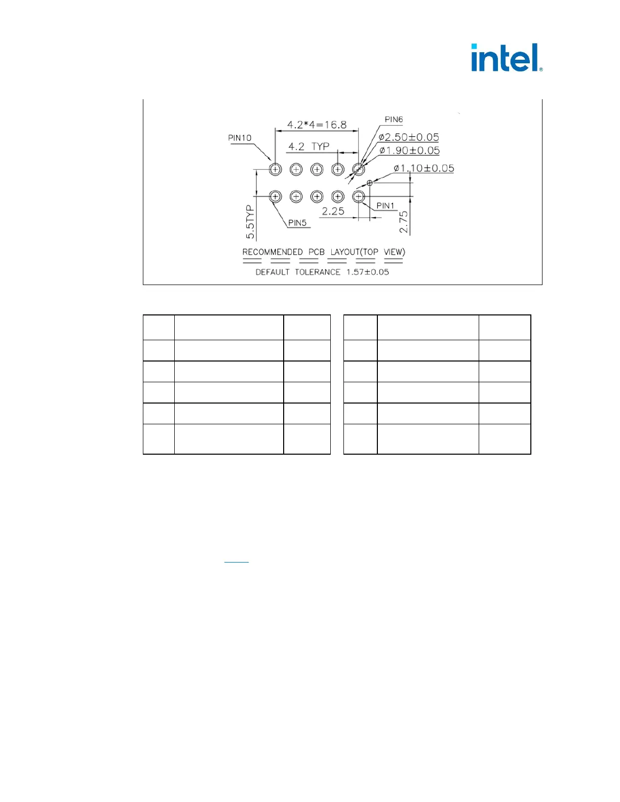
Table 5-2: Main Power Connector Pinout
Pin Signal Color
Pin Signal Color
1
PS_ON# Green
6
PWR_OK Gray
2
COM Black
7
+12VSB Purple
3
COM Black
8
+12V1 DC Yellow
4
COM Black
9
+12V1 DC Yellow
5
I_PSU% Blue
10
+12V1 DC
[12V Sensing Pin]
Yellow
[Brown]
This power connector is designed as the main board connector and for smaller to
medium size boards this is the only connector that is needed. This connector can
provide up to 216 to 288 watts of power using the assumption that each pin can
provide 6–8 Amps. Board designers need to figure out total board power and if this
single connector provides enough power for each board.
Pin 10 is used for both main 12V Power and the optional Voltage Sensing wire for the
power supply to provide the correct voltage to the motherboard. Voltage Sensing Pin
details in Section 4.2.3
.
5.2.2.2 Extra Board Connector (Based on PSU Size)
If board power requirements are higher than what can be provided by the 10 pin Main
Board Connector, the Extra Board Power connector can be used. This connector can
provide an additional 216-288 watts of power to the motherboard to support multiple
PCIe* connectors, multiple USB ports, or other expansion slots.
Two connectors can also be used if the 240VA Safety requirements are needed for the
PSU.
Since the Extra Board Connector is optional on the motherboard and is expected to be
needed only for higher power motherboards, this can be correlated to PSU size.