Datasheet 31
Intel
®
Celeron
®
Processor up to 1.10 GHz
NOTES:
1. Unless otherwise noted, all specifications in this table apply to all Celeron processor frequencies and cache
sizes.
2. V
IH
and V
OH
for the Intel Celeron processor may experience excursions of up to 200 mV above VTT for a
single system bus clock. However, input signal drivers must comply with the signal quality specifications in
Section 3.0.
3. Minimum and maximum V
TT are given in Table 8.
4. Parameter correlated to measurement into a 25 Ω resistor terminated to 1.5 V.
5. I
OH
for the Intel Celeron processor may experience excursions of up to 12 mA for a single system bus clock.
6. (0 ≤ V
IN ≤ 2.0 V +5%) for S.E.P Package and PPGA Package; (0 ≤ VIN ≤ 1.5V +3%) for FC-PGA/FC-PGA2
packages.
7. (0 ≤ V
OUT ≤ 2.0 V +5%) for S.E.P Package and PPGA Package; (0 ≤ VOUT ≤ 1.5V +3%) for FC-PGA/
FC-PGA2 packages.
8. Refer to the I/O Buffer Models for IV characteristics.
9. Steady state input voltage must not be above V
SS
+ 1.65 V or below VTT - 1.65 V.
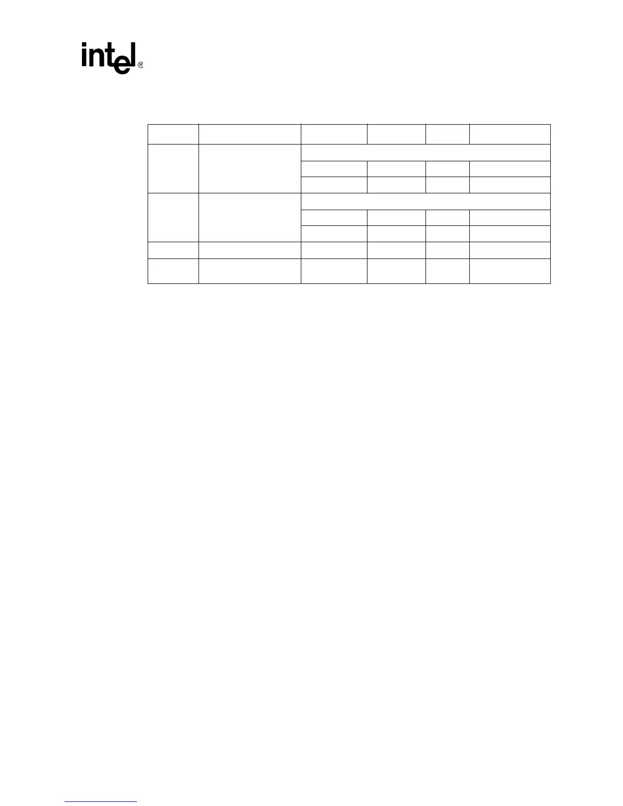
Table 6. AGTL+ Signal Groups DC Specifications
Symbol Parameter Min Max Unit Notes
V
IL
Input Low Voltage
• S.E.P.P and PPGA –0.3 0.82 V
• FC-PGA/FC-PGA2 –0.150 V
REF – 0.200 V 9
V
IH
Input High Voltage
• S.E.P.P and PPGA 1.22 V
TT V2, 3
•FC-PGA/FC-PGA2 V
REF + 0.200 VTT V2, 3
R
ON
Buffer On Resistance 16.67 Ω 8
I
L
Leakage Current for
inputs, outputs, and I/O
±100 µA 6, 7