EasyManuals Logo
Home>Intel>Computer Hardware>CELERON 1.10 GHZ

Intel CELERON 1.10 GHZ User Manual

Intel CELERON 1.10 GHZ
128 pages
To Next Page IconTo Next Page
To Previous Page IconTo Previous Page
Page #70 background imageLoading...
Page #70 background image
70 Datasheet
Intel
®
Celeron
®
Processor up to 1.10 GHz
5.1.2 Signal Listing (S.E.P. Package)
Table 45 and Table 46 provide the processor edge finger and SC242 connector signal definitions
for Celeron processor. The signal locations on the SC242 edge connector are to be used for signal
routing, simulation, and component placement on the motherboard.
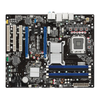
Figure 19. Processor Substrate Dimensions (S.E.P. Package)
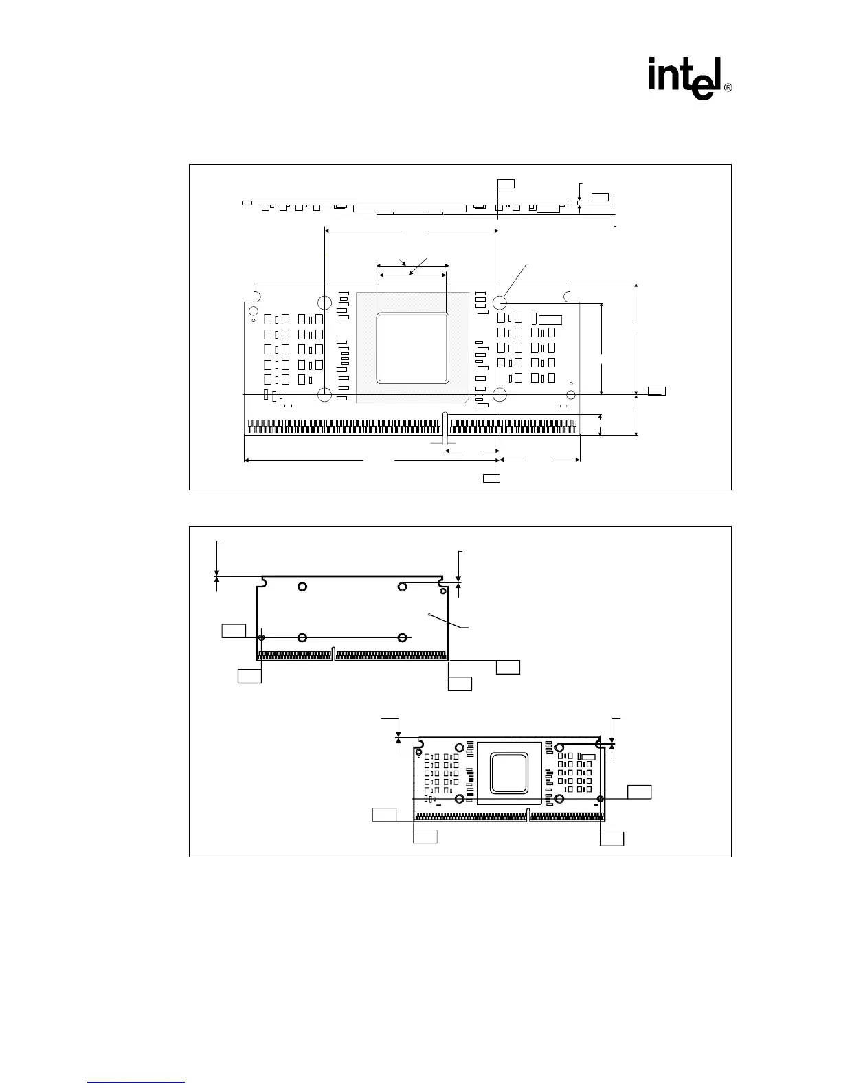
Figure 20. Processor Substrate Primary/Secondary Side Dimensions (S.E.P. Package)
-Y-
1.660
.615
1.196
3.804
.814
.323
2.608
1.370
-Y-
27.4 mm SR
Opening Square
25.4 mm Copper
Slug Square
-Z-
-Y-
.062
+.007
-.005
-E-
-D-
-G-
-H-
-E-
-D-
-G-
-H-
Typ Max.
Non-Keepout Area
.025
Typ Max.
Non-Keepout Ar
e
.025
Typ Max.
Non-Keepout Area
.025
Typ Max.
Non-Keepout Area
.025
Secondary Side
Primary Side
There Will be No Components on
Secodonary Side

Table of Contents

Questions and Answers:

Question and Answer IconNeed help?

Do you have a question about the Intel CELERON 1.10 GHZ and is the answer not in the manual?

Intel CELERON 1.10 GHZ Specifications

General IconGeneral
BrandIntel
ModelCELERON 1.10 GHZ
CategoryComputer Hardware
LanguageEnglish

Related product manuals