Datasheet 55
Intel
®
Celeron
®
Processor up to 1.10 GHz
3.2 AGTL+ Signal Quality Specifications and Measurement
Guidelines
Many scenarios have been simulated to generate a set of AGTL+ layout guidelines which are
available in AP-585, Pentium
®
II Processor AGTL+ Guidelines (Order Number 243330). Refer to
the Pentium
®
II Processor Developer's Manual (Order Number 243502) for the AGTL+ buffer
specification.
Table 31 provides the AGTL+ signal quality specifications (for both the S.E.P. and PPGA
Packages) for use in simulating signal quality at the processor core. Table 32 provides the AGTL+
signal quality specifications (for the FC-PGA/FC-PGA2 packages) for use in simulating signal
quality at the processor core. Table 33 provides AGTL+ signal quality guidelines for measuring and
testing signal quality at the processor edge fingers. Figure 13 describes the signal quality waveform
for AGTL+ signals at the processor core and edge fingers. For more information on the AGTL+
interface, see the Pentium
®
II Processor Developer's Manual (Order Number 243502).
NOTES:
1. Unless otherwise noted, all specifications in this table apply to all Celeron processor frequencies.
2. Specifications are for the edge rate of 0.3 – 0.8 V/ns. See Figure 13 for the generic waveform.
3. All values specified by design characterization.
4. This specification applies to Intel Celeron processors operating with a 66 MHz Intel Celeron processor
system bus only.
5. Ringback below V
REF + 20 mV is not supported.
NOTES:
1. Unless otherwise noted, all specifications in this table apply to all Celeron processor frequencies.
2. Specifications are for the edge rate of 0.3 – 0.8V/ns. See Figure 13 for the generic waveform.
3. All values specified by design characterization.
4. See Table 36 for maximum allowable overshoot.
5. Ringback between V
REF + 100 mV and VREF + 200 mV or VREF – 200 mV and VREF – 100 mVs requires the
flight time measurements to be adjusted as described in the Intel AGTL+ Specifications (
Intel
®
Pentium
®
II
Developers Manual
). Ringback below VREF + 100 mV or above VREF – 100 mV is not supported.
6. Intel recommends simulations not exceed a ringback value of V
REF ±200 mV to allow margin for other
sources of system noise.
7. A negative value for
ρ indicates that the amplitude of ringback is above VREF. (i.e., φ = –100 mV specifies the
signal cannot ringback below V
REF + 100 mV).
8.
φ and ρ: are measured relative to VREF. α: is measured relative to VREF + 200 mV.
9. All Ringback entering the Overdrive Region must have flight time correction.
10.Overshoot specifications for Ringback do not correspond to Overshoot specifications in Section 3.4.
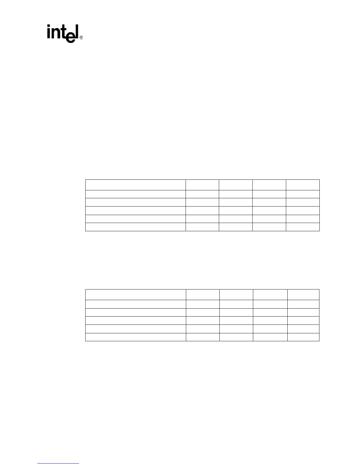
Table 31. AGTL+ Signal Groups Ringback Tolerance Specifications at the Processor Core
(For Both the S.E.P. and PPGA Packages)
T# Parameter Min Unit Figure Notes
α
: Overshoot 100 mV 13 4
τ: Minimum Time at High 1.00 ns 13 4
ρ: Amplitude of Ringback –100 mV 13 4, 5
φ: Final Settling Voltage 100 mV 13 4
δ: Duration of Squarewave Ringback N/A ns 13
Table 32. AGTL+ Signal Groups Ringback Tolerance Specifications at the Processor Pins
(For FC-PGA/FC-PGA2 Packages)
T# Parameter Min Unit Figure Notes
α
: Overshoot 100 mV 13 4, 8, 9, 10
τ: Minimum Time at High 0.50 ns 13 9
ρ: Amplitude of Ringback –200 mV 13 5, 6, 7, 8
φ: Final Settling Voltage 200 mV 13 8
δ: Duration of Squarewave Ringback N/A ns 13