Datasheet 39
Intel
®
Celeron
®
Processor up to 1.10 GHz
NOTES:
1. Unless otherwise noted, all specifications in this table apply to all Celeron processor frequencies.
2. Not 100% tested. Specified by design characterization.
3. All AC timings for the AGTL+ signals are referenced to the BCLK rising edge at 0.50 V at the processor edge
fingers. All AGTL+ signal timings (compatibility signals, etc.) are referenced at 1.00 V at the processor edge
fingers.
4. This specification applies to Intel Celeron processors operating with a 66 MHz Intel Celeron processor
system bus only.
5. Valid delay timings for these signals are specified into 50 Ω to 1.5 V and with V
REF at 1.0 V.
6. A minimum of 3 clocks must be guaranteed between two active-to-inactive transitions of TRDY#.
7. RESET# can be asserted (active) asynchronously, but must be deasserted synchronously.
8. Specification is for a minimum 0.40 V swing.
9. Specification is for a maximum 1.0 V swing.
10.After V
CC
CORE
, and BCLK become stable.
NOTES:
1. Unless otherwise noted, all specifications in this table apply to all Intel
®
Celeron
®
processor frequencies.
2. These specifications are tested during manufacturing.
3. All AC timings for the AGTL+ signals are referenced to the BCLK rising edge at 1.25 V at the processor core
pin. All AGTL+ signal timings (compatibility signals, etc.) are referenced at 1.00 V at the processor core pins.
4. This specification applies to the Intel Celeron processor operating with a 66 MHz Intel Celeron processor
system bus only.
5. Valid delay timings for these signals are specified into 25 Ω to 1.5 V and with V
REF at 1.0 V.
6. A minimum of 3 clocks must be guaranteed between two active-to-inactive transitions of TRDY#.
7. RESET# can be asserted (active) asynchronously, but must be deasserted synchronously.
8. Specification is for a minimum 0.40 V swing.
9. Specification is for a maximum 1.0 V swing.
10.After V
CC
CORE
and BCLK become stable.
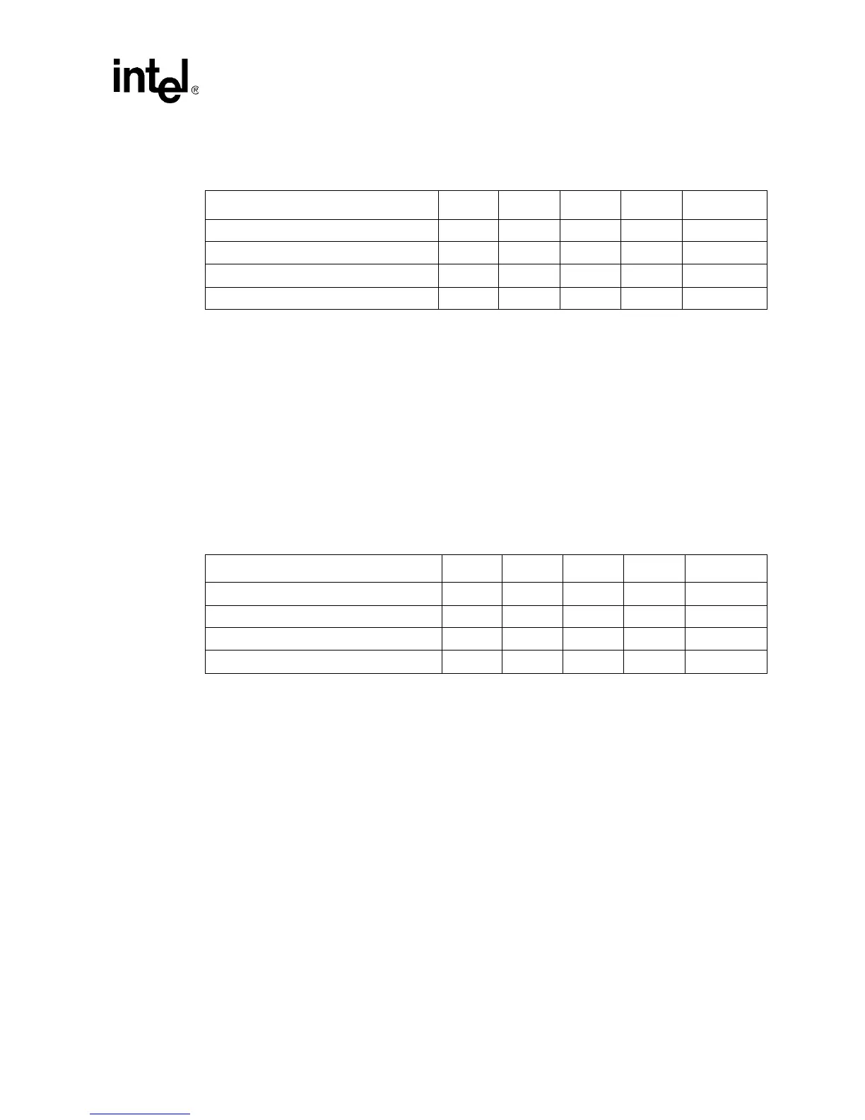
Table 13. System Bus AC Specifications (AGTL+ Signal Group) at the Processor Edge
Fingers (for S.E.P. Package)
T# Parameter Min Max Unit Figure Notes
T7’: AGTL+ Output Valid Delay 1.07 6.37 ns 4 4, 5
T8’: AGTL+ Input Setup Time 1.96 ns 5 4, 6, 7, 8
T9’: AGTL+ Input Hold Time 1.53 ns 5 4, 9
T10’: RESET# Pulse Width 1.00 ms 6 10
Table 14. System Bus AC Specifications (AGTL+ Signal Group) at the Processor Core Pins
(for S.E.P. Package)
T# Parameter Min Max Unit Figure Notes
T7: AGTL+ Output Valid Delay 0.17 5.16 ns 4 5
T8: AGTL+ Input Setup Time 2.10 ns 5 5, 6, 7, 8
T9: AGTL+ Input Hold Time 0.77 ns 5 9
T10: RESET# Pulse Width 1.00 ms 6 7, 10