24 Datasheet
Intel
®
Celeron
®
Processor up to 1.10 GHz
NOTES:
1. Operating voltage is the voltage to which the component is designed to operate. See Table 5.
2. This rating applies to the V
CC
CORE
, VCC
5
, and any input (except as noted below) to the processor.
3. Parameter applies to CMOS, APIC, and TAP bus signal groups only.
4. The electrical and mechanical integrity of the processor edge fingers are specified to last for 50 insertion/
extraction cycles.
5. S.E.P. Package Only
6. PGA Packages Only
7. Input voltage can never exceed V
SS + 2.8 volts.
8. Input voltage can never go below V
TT - 2.18 volts.
9. Parameter applies to CMOS (except BCLK, PICCLK, and PWRGOOD), APIC, and TAP bus signal groups
only for VinCMOS on the FC-PGA/FC-PGA2 Packages only.
10.Parameter applies to CMOS signals BCLK, PICCLK, and PWRGOOD for VinCMOS1.5 on FC-PGA/
FC-PGA2 Package only.
2.10 Processor DC Specifications
The processor DC specifications in this section are defined for the Celeron processor. See
Section 7.0 for signal definitions and Section 5.0 for signal listings.
Most of the signals on the Intel Celeron processor system bus are in the AGTL+ signal group.
These signals are specified to be terminated to 1.5 V. The DC specifications for these signals are
listed in Table 6.
To allow connection with other devices, the Clock, CMOS, APIC, and TAP signals are designed to
interface at non-AGTL+ levels. The DC specifications for these pins are listed in Table 7.
Table 5 through Table 8 list the DC specifications for Intel Celeron processors operating at 66 MHz
Intel Celeron processor system bus frequencies. Specifications are valid only while meeting
specifications for case temperature, clock frequency, and input voltages. Care should be taken to
read all notes associated with each parameter.
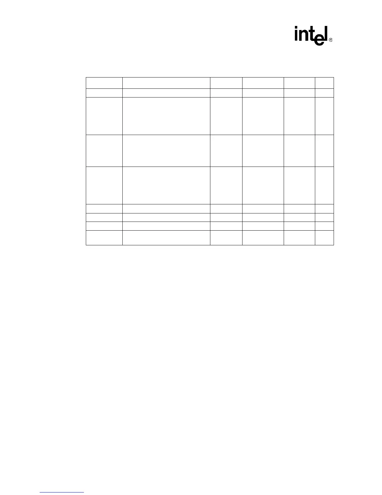
Table 4. Absolute Maximum Ratings
Symbol Parameter Min Max Unit Notes
T
STORAGE
Processor storage temperature –40 85 °C
V
CC(All)
Any processor supply voltage with
respect to V
SS
• PPGA and S.E.P.P. –0.5
Operating
voltage + 1.0
V1, 2
• FC-PGA/FC-PGA2 –0.5 2.1 V
VinAGTL+
AGTL+ buffer DC input voltage with
respect to V
SS
• PPGA and S.E.P.P. –0.3 VCC
CORE
+ 0.7 V
•FC-PGA/FC-PGA2 V
TT - 2.18 2.18 V 7, 8
VinCMOS
CMOS buffer DC input voltage with
respect to V
SS
• PPGA and S.E.P.P. -0.3 3.3 V 3
•FC-PGA/FC-PGA2 V
TT - 2.18
-0.58
2.18
3.18
V
V
7, 8, 9
10
I
VID Max VID pin current 5 mA
I
SLOTOCC# Max SLOTOCC# pin current 5 mA 5
I
CPUPRES# Max CPUPRES# pin current 5 mA 6
Mech Max
Edge Fingers
5
Mechanical integrity of processor
edge fingers
50
Insertions/
Extractions
4, 5