50 Datasheet
Intel
®
Celeron
®
Processor up to 1.10 GHz
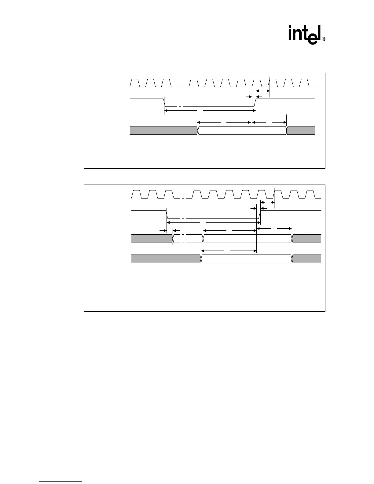
Figure 6. System Bus Reset and Configuration Timings (For the S.E.P. and PPGA Packages)
Figure 7. System Bus Reset and Configuration Timings (For the FC-PGA/FC-PGA2 Package)
Valid
T
v
T
w
T
x
T
u
T
t
BCLK
RESET#
Configuration
(A[14:5]#, BR0#,
FLUSH#, INT#)
T
t
= T9 (AGTL+ Input Hold Time)
T
u
= T8 (AGTL+ Input Setup Time)
T
v
= T10 (RESET# Pulse Width)
T
w
= T16 (Reset Configuration Signals (A[14:5]#, BR0#, FLUSH#, INIT#) Setup Time)
T
x
= T17 (Reset Configuration Signals (A[14:5]#, BR0#, FLUSH#, INIT#) Hold Time)
T
y
Safe Valid
T
z
Valid
T
v
T
w
T
x
T
u
T
t
BCLK
RESET#
Configuration
(A20M#, IGNNE#,
LINT[1:0])
Configuration
(A[14:5]#, BR0#,
FLUSH#, INT#)
T
t
= T9 (AGTL+ Input Hold Time)
T
u
= T8 (AGTL+ Input Setup Time)
T
v
= T10 (RESET# Pulse Width)
T
w
= T16 (Reset Configuration Signals (A[14:5]#, BR0#, FLUSH#, INIT#) Setup Time)
T
x
= T17 (Reset Configuration Signals (A[14:5]#, BR0#, FLUSH#, INIT#) Hold Time)
T20 (Reset Configuration Signals (A20M#, IGNNE#, LINT[1:0]) Hold Time)
Ty = T19 (Reset Configuration Signals (A20M#, IGNNE#, LINT[1:0]) Delay Time)
Tz = T18 (Reset Configuration Signals (A20M#, IGNNE#, LINT[1:0]) Setup Time)