Product Description
23
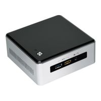
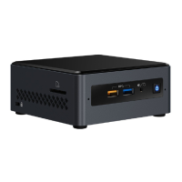
1.6 USB
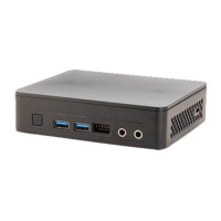
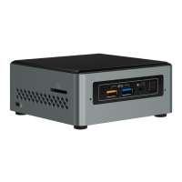
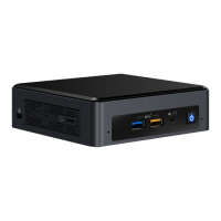
The USB port arrangement is as follows:
• USB 3.0 ports (maximum current is 900 mA for each blue port, 1.5 A for the orange charging
port):
Two ports are implemented with external front panel connectors (one blue and one
orange charging capable)
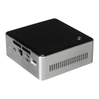
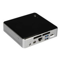
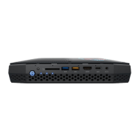
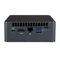
Two ports are implemented with external back panel connectors (blue)
• USB 2.0 ports (maximum current is 500 mA for each port of the white header (1 A total):
Two ports via one dual-port internal 1x8 1.25 mm pitch header (white)
One port is reserved for an M.2 2230 for the Wireless module
All the USB ports are high-speed, full-speed, and low-speed capable.
NOTE
Computer systems that have an unshielded cable attached to a USB port may not meet FCC
Class B requirements, even if no device is attached to the cable. Use a shielded cable that meets
the requirements for full-speed devices.
For information about Refer to
The location of the USB connectors on the back panel Figure 11, page 38
The location of the USB connector on the front panel
1.7 SATA Interface
The SoC provides one SATA port with a theoretical maximum transfer rate of 6.0 Gb/s. A point-to-
point interface is used for host to device connections.
The underlying SATA functionality is transparent to the operating system. The SATA controller
can operate in both legacy and native modes. In legacy mode, standard IDE I/O and IRQ resources
are assigned (IRQ 14 and 15). In Native mode, standard PCI Conventional bus resource steering is
used. Native mode is the preferred mode for configurations using Windows* operating systems.
1.7.1 AHCI Mode
The board supports AHCI storage mode.
NOTE
In order to use AHCI mode, AHCI must be enabled in the BIOS. Microsoft* Windows 8 includes the
necessary AHCI drivers without the need to install separate AHCI drivers during the operating
system installation process. However, it is always good practice to update the AHCI drivers to the
latest available by Intel.
 Loading...