Technical Reference
47
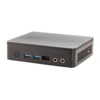
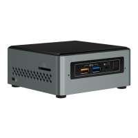
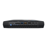
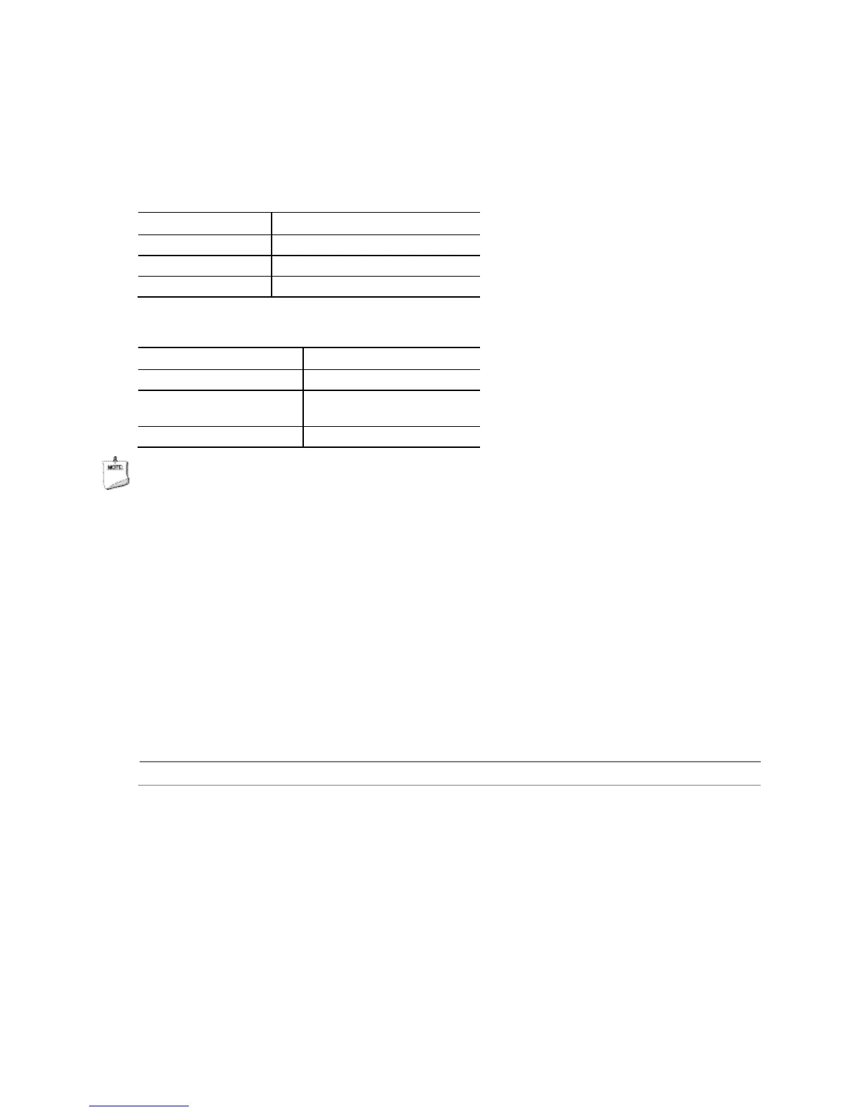
2.2.4.5.3 Power/Sleep LED Header
Pins 2 and 4 can be connected to a one- or two-color LED. Table 18 and Table 19 show the
possible LED states.
Table 18. States for a One-Color Power LED
Table 19. States for a Dual-Color Power LED
LED State Description
Off Power off
(amber)
Primary color steady (white)
NOTE
The LED behavior shown in Table 18 is default – other patterns may be set via BIOS setup.
2.2.4.5.4 Power Switch Header
Pins 6 and 8 can be connected to a front panel momentary-contact power switch. The switch
must pull the SW_ON# pin to ground for at least 50 ms to signal the power supply to switch on or
off. (The time requirement is due to internal debounce circuitry on the board.) At least two
seconds must pass before the power supply will recognize another on/off signal.
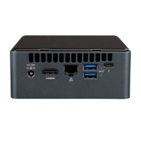
2.2.4.5.5 5V DC Power Header
Pin 6 can supply 2A of 5V DC (VCC) power. Any usage of power from this header should be
considered when calculating the system’s total power budget.
Power supply considerations Section 2.5.1, page 53
 Loading...