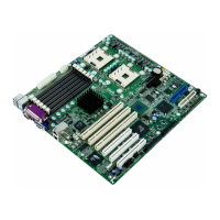
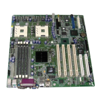
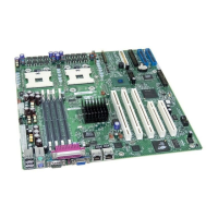
SE7500CW2 Server Board Technical Product Specification Included PCI Devices
21
Revision 1.40
• 4 pin header for off board LEDs
Pin-out for the card is as follows:
Table 6. Optional Intel® 53C1000B1 SCSI card pin-out(J1)
Pin Signal Name
1 +5V
2 LED1_L
3 LED1_L
4 +5V
4.5 Interrupt Routing
The SE7500CW2 interrupt architecture accommodates both PC-compatible PIC mode and
APIC mode interrupts through use of the integrated I/O APICs in the ICH3-S.
4.5.1 Legacy Interrupt Routing
For PC-compatible mode, the ICH3-S provides two 82C59-compatible interrupt controllers. The
two controllers are cascaded with interrupt levels 8-15 entering on level 2 of the primary interrupt
controller (standard PC configuration). A single interrupt signal is presented to the processors, to
which only one processor will respond for servicing. The ICH3-S contains configuration registers
that define which interrupt source logically maps to I/O APIC INTx pins.
Interrupts, both PCI and IRQ types, are handled by the ICH3-S. The ICH3-S then translates these
to the APIC bus. The numbers in the table below indicate the ICH3-S PCI interrupt input pin to
which the associated device interrupt (INTA, INTB, INTC, INTD) is connected. The ICH3-S’ I/O
APIC exists on the I/O APIC bus with the processors.
Table 7. PCI Interrupt Routing/Sharing
Interrupt INT A INT B INT C INT D
ATI Rage SL ICH3_PIRQF_L
Promise ATA-100 Controller ICH3_PIRQG_L
82550PM #2 ICH3_PIRQE_L
82550PM #1 ICH3_PIRQH_L
P64H2 BT INTR# ICH3_PIRQC# (for PIC mode)
P64-C Slot 1 P1_IRQ0_L P1_IRQ1_L P1_IRQ2_L P1_IRQ3_L
P64-B Slot 2 P2_IRQ0_L P2_IRQ1_L P2_IRQ2_L P2_IRQ3_L
P64-B Slot 3 P2_IRQ4_L P2_IRQ5_L P2_IRQ6_L P2_IRQ7_L
P32-A Slot 4 ICH3_PIRQB_L ICH3_PIRQC_L ICH3_PIRQB_L ICH3_PIRQC_L
P32-A Slot 5 ICH3_PIRQD_L ICH3_PIRQA_L ICH3_PIRQD_L ICH3_PIRQA_L
 Loading...
