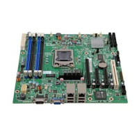
SE7500CW2 Server Board Technical Product SpecificationSE7500CW2 Connectors and Jumper Blocks
93
Revision 1.40
8.13 Serial Port Connectors
Two serial ports are provided on the server board.
• A standard, external DB9 serial connector is located on the back edge of the baseboard
to supply a Serial 1 interface
• A Serial 2 port is provided through a 9-pin header on the server board.
The following tables detail the pin-outs of these two ports.
Table 57. External DB9 Serial 1 Port Pin-out (J44)
Pin Signal Name Description
1 OCDCD1_L
Carrier Detect or Data Set Ready
1
2 OCSIN1_H Receive Data
3 OCSOUT1_H Transmit Data
4 OCDTR1_L Data Terminal Ready
5 GND Signal Ground
6 OCDSR1_L Request To Send
7 OCRTS1_L
Carrier Detect or Data Set Ready
1
8 OCCTS1_L Clear to send
9 OCRI1_L Ring Indicate
Table 58. 9-pin Header Serial 2 Port Pin-out (J28)
Pin Signal Name
1 OCDCD2_L
(carrier detect)
2 OCDSR2_L (Data
Set Ready)
3 OCSIN2_H
(Receive Data)
4 OCRTS2_L
(Clear to Send)
5 OCSOUT2_H
(Transmit Data)
6 OCCTS2_L
(Request to Send)
7 OCDTR2_L
(Data Terminal Ready)
8 OCRI2_L
(Ring Indicate)
9 (Ground)
 Loading...
