23
System Board
You must swap the DIMMs and processor module(s) from the old system board to the new
one if you replace the system board. See the system board diagram in Chapter 5, “System
Board,” for connector and socket locations.
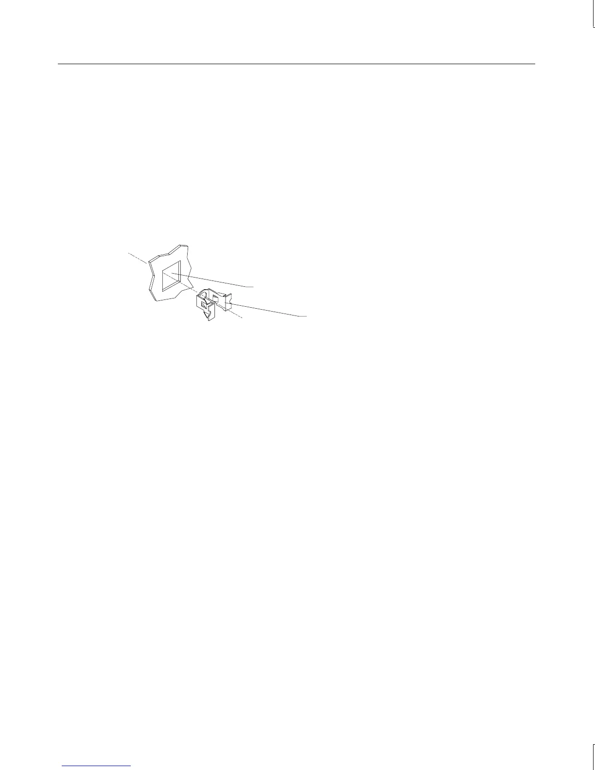
Note that a number of Fastex fasteners are mounted in the right side of the chassis to secure
the system board and support for the processor retention modules. Do not overtighten the
screws to these fasteners. If overtightened, the fasteners may distort.
Fastex fastener
Hole in right side of chassis
To remove the system board:
1. Lay the chassis down on its right side.
2. Note the locations where all cables are connected to the system board.
3. Disconnect all cables from the system board.
4. Note the locations of the expansion cards, remove them, and place the cards on an
antistatic surface.
5. Remove the air duct covering the processor module(s). See the “Power Supply” section
above for details.
6. Remove DIMMs and processor module(s) and place them on an antistatic surface. See
the respective procedures above for details on removing these components.
7. Remove the jackscrews on all external port connectors.
WARNING Use care when removing or installing the screws to avoid damaging components on
the system board.
8. Remove the screws and the plastic rivets on the processor retention module(s), and
remove the retension module(s) from the chassis.
9. Remove the screws from the system board.
10. Lift the system board out of the chassis and place it on an antistatic surface.