27
LEDs, Light Pipe, and Power Switch
See the system board diagram in Chapter 5, “System Board,” for connector and socket
locations. See also the “Cable Routing and Pinouts” section in Chapter 5 for LED and power
switch cable and connector details.
To replace an LED:
1. Remove the internal bay disk drives. See the “Internal Bay Disk Drives” section for
details.
2. Note the locations of each of the LEDs on the light pipe.
3. Remove the LED from its mount on the light pipe, then disconnect the LED cable from
its connector on the system board.
4. Remove the LED cable from the chassis.
5. Route the new LED cable through the chassis and connect it to the appropriate
connector on the system board.
6. Press the LED into its mount on the light pipe.
To replace the light pipe:
1. Remove the face panel. See the “Case Components” section earlier in this chapter for
details.
2. Remove the internal bay disk drives. See the “Internal Bay Disk Drives” section earlier
in this chapter for details.
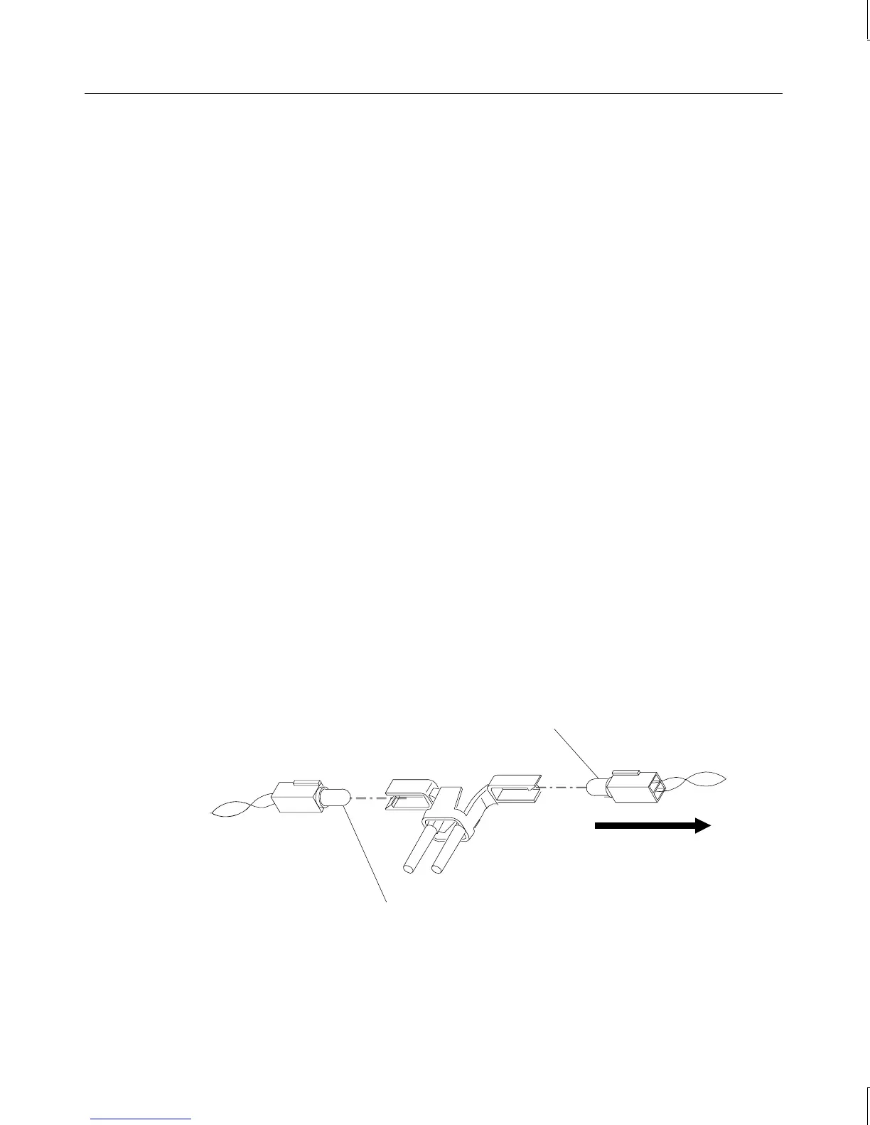
3. Disconnect the LEDs from the light pipe.
Power LED
black/white wires
Disk activity LED
(black/orange wires)
Top of chassis
4. Squeeze the mounting tabs on the light pipe inward and push the light pipe through its
mounting hole.