Chapter 2: Installation
22 NS3552-8P-2S-V2 User Manual
System
Color Function
Green Lit: indicates that the DC power input 1 has power.
2 Green Lit: indicates that the DC power input 2 has power.
ault Green Lit: indicates that switch DC or port has failed.
Green Lit: indicates that the ERPS ring has been sucessfully created.
Green
Lit: indicates that the ring state is in idle mode.
Blinking: indicates that the ring state is in protected mode.
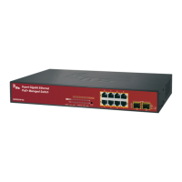
Per 10/100/1000 port with PoE
LED Color Function
10/100/1000
LNK/ACT
Green Lit: indicates the port has successfully connected to the
network.
Blinking: indicates that the switch is actively sending or
receiving data over that port.
PoE in use Orange Lit: indicates the port is providing 48/56 VDC in-line power.
Off: indicates that the connected device is not a PoE
powered device (PD).
Per SFP interface (port 9, port 10 mini-GBIC)
LED Color Function
LNK/ACT
Green Lit: indicates the port has successfully connected to the
network.
Blinking: indicates that the switch is actively sending or
receiving data over that port.
1000 Orange Lit: indicates the port has successfully connected to the
network at 1000 Mbps.
Blinking: indicates that the switch is actively sending or
receiving data over that port.
Wiring the power input
The rear panel of the industrial managed switch contains a DC inlet power socket and
one terminal block connector with six contacts.
1. Insert positive/negative DC power wires into contacts 1 and 2 for DC Power 1, or 5
and 6 for DC Power 2.
Caution: Do not plug a DC power connector into the device while power is ON, as this
will cause damage to the unit. This is NOT a hot-swappable device.