Chapter 2: Installation
NS3552-8P-2S-V2 User Manual 23
2. Tighten the wire-clamp screws to prevent the wires from loosening.
Note:
1. The wire gauge for the terminal block should be in the range of 12 to 24 AWG.
2. When performing any of the procedures such as inserting the wires or tightening the
wire-clamp screws, make sure the power is OFF to avoid electrical shock.
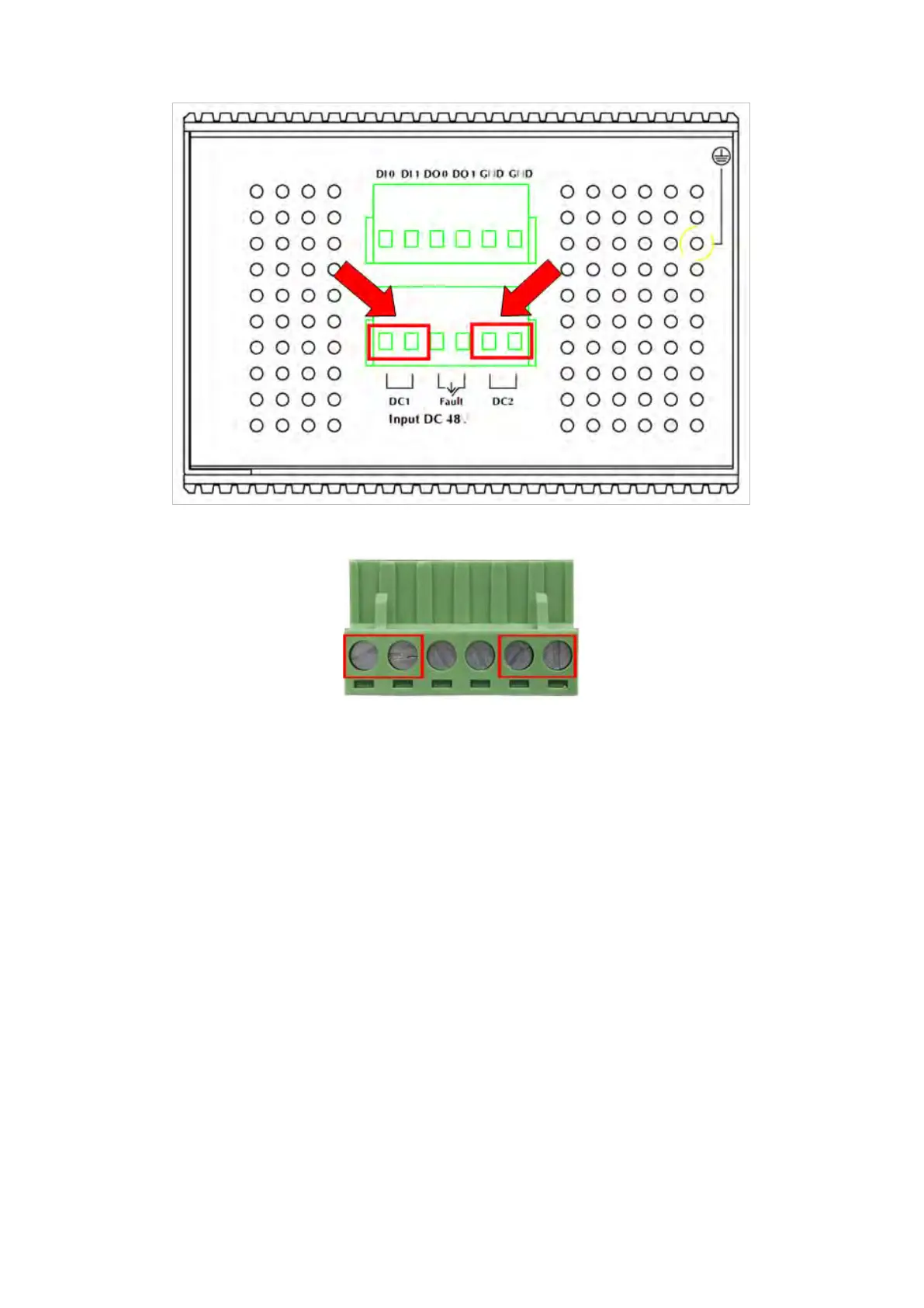
Wiring the fault alarm contact
The fault alarm contacts are in the middle (3 & 4) of the terminal block connector as the
picture shows below. Inserting the wires, the industrial managed switch detects the fault
status of the power failure, or port link failure. The following illustration shows an
application example for wiring the fault alarm contacts. Wires are inserted into the fault
alarm contacts.