Chapter 2: Installation
24 NS3552-8P-2S-V2 User Manual
Note:
1. The wire gauge for the terminal block should be in the range of 12 to 24 AWG.
2. When performing any of the procedures such as inserting the wires or tightening the
wire-clamp screws, make sure the power is OFF to avoid electrical shock.
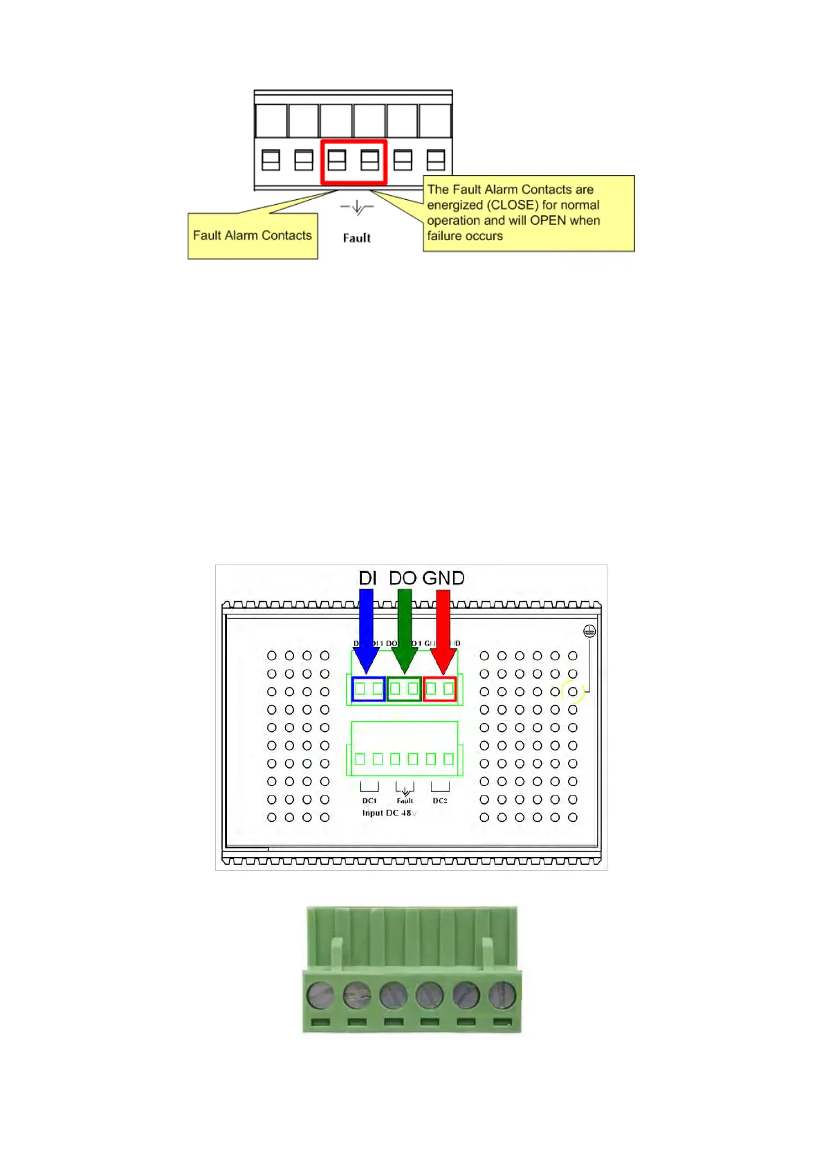
Wiring the digital input/output
The 6-contact terminal block connector on the rear panel of the industrial managed
switch is used for digital input and digital output. Please follow the steps below to insert
wires.
1. The industrial managed switch offers two DI and DO groups. 1 and 2 are DI groups;
3 and 4 are DO groups; and 5 and 6 are GND (ground).
2. Tighten the wire-clamp screws for preventing the wires from loosening.