Chapter 1 — Replacing Parts
CV30 Fixed Mount Computer Service Manual 11
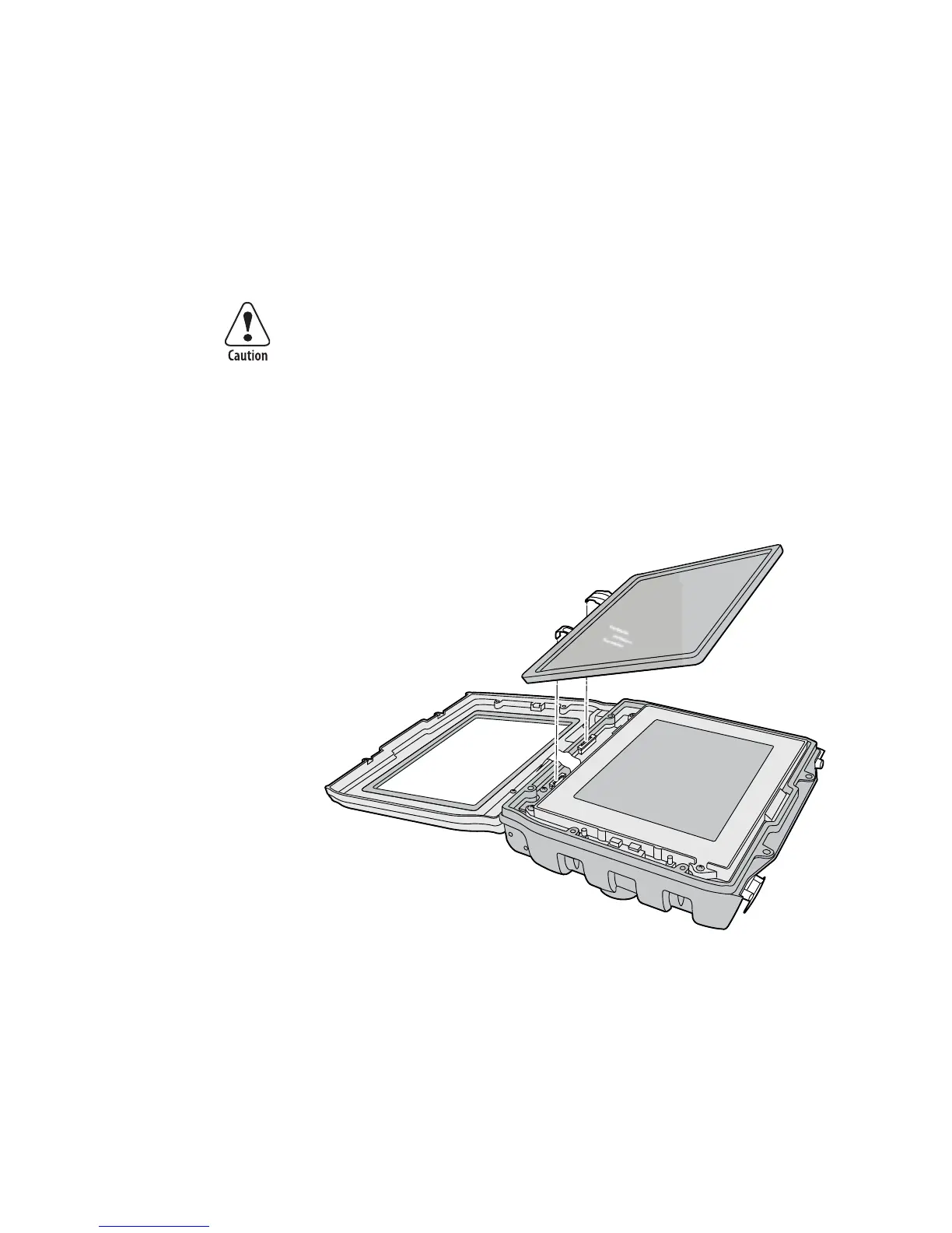
To replace the display frame assembly
1 Open the top cover. For help, see “Opening the Top Cover (Radome)”
on page 2.
2 Open the front cover. For help, see “Opening the Front Cover” on
page 4.
3 Use the flathead screwdriver to release the two flex connectors that
connect the touch panel to the CV30.
4 Lift the touch panel assembly away from the CV30.
5 Remove the four 4-40 x 3/8 inch Phillips screws that attach the display
frame to the CV30 base.
The flex connectors are called zero insertion force (ZIF) connectors
and they are very fragile. To avoid breaking the connectors, open and
close them carefully. Do not apply excessive pressure to the movable
part of the connector when opening and closing it.
Vorsicht: Die Flex-Steckverbinder werden als ZIF-Steckverbinder
(Zero Insertion Force) bezeichnet und sind extrem zerbrechlich. Die
Steckverbinder müssen vorsichtig geöffnet und geschlossen werden,
damit sie nicht beschädigt werden. Beim Öffnen und Schließen
keinen starken Druck auf den beweglichen Teil des Steckverbinders
ausüben.