Chapter 3 — Theory of Operation
CV30 Fixed Mount Computer Service Manual 65
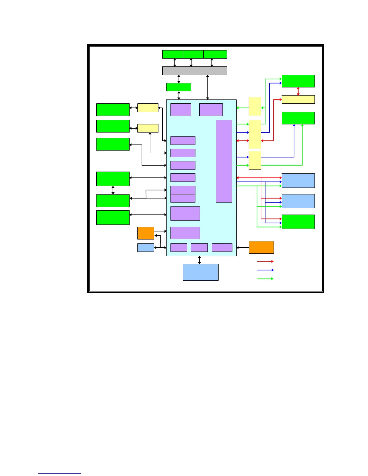
Main Processor Functional Diagram
RTC (Real Time Clock)
The main processor has an internal real time clock, but it does not retain
time through a cold reset. To work around this limitation, an external
clock IC was implemented to allow the time settings to bridge cold resets.
The processor communicates with the clock chip through a two-wire I2C
bus and can set the time in both the internal and external RTC via a
software utility. The external RTC chip provides an accurate 32 KHz clock
for the main processors internal RTC to use. The CV30 uses the Epson
RTC-8564NB(LF).
Main Processor
The main processor has an ARM 4 core with several functional modules
attached internally to the IC. Several clocking options are allowed to
maximize performance. This is a RISC processor. 64 MB of Intel flash are
stacked above the processor die in the same chip.
BULVERDE
PXA270
520M HZ
BLUETOOTH
MODULE
36.768kHz
OSC
POWER
MANAGEMENT
M ax1587C
128M B
SDRAM
128M B
FLASH
RTC
FF UART
BT UART
ST UART
AC 97
I2S
SD/MM C
IN TE R FA CE
CLOCK
XTAL
13MHZ
AC97
AUDIO
SDIO
CONN
RS232
COM1
RS232
COM2
TOUCH
CONTROLLER
USB
HOST
USB
CLIENT
TXCVR
TXCVR
TXCVR
USB HUB
ETHERNET
CONTROLLER
I2C PIC I2C
MEMORY
CONTROLLER
RADIO
802.11b/
BUS SW ITCH
DSUB 15P CONN
HOST 1 HOST 2 CLIENT
SSP
TXCVR TXCVR
DATA BUS
ADDRESS BUS
CONTROL LINES