Intermec EasyCoder F2 – Installation & Operation Ed. 2 99
Appendix 3 Interfaces
1
/. Nibble, byte, ECP and EPP
from printer to host are presently
not supported.
2
/. Intermec Shell either auto-
matically sets the correct std IN
and OUT port when an applica-
tion is selected, e.g. a Windows
driver, or prompts you to select
one, see chapter 8.
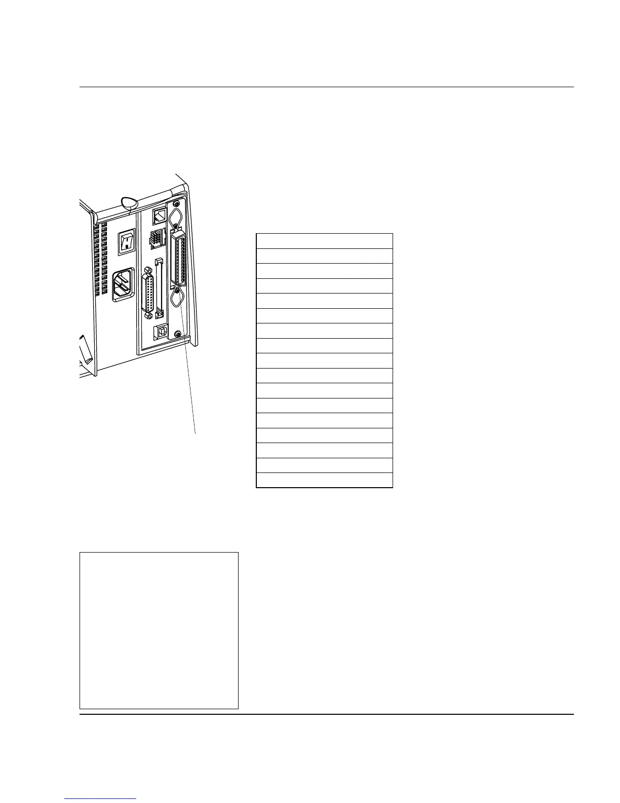
IEEE 1284
Parallel Interface
Board
The EasyCoder F2 can optionally be fi tted with an IEEE 1284-I
compatible parallel interface board
1
. The parallel port is addressed
in Intermec Fingerprint as device "centronics:". Select "centronics:"
as standard IN port by means of the instruction SETSTDIO (by
default, "uart1:" in std IN port)
2
.
Interface Cable Connectors
Computer end: Depends on type of host computer.
Printer end: 36 pin female IEEE 1284B Centron
Pin Signal Name
1 DStrobe
2–9 Data 0–7
10 Ack
11 Busy
12 PE
13 Select
14 AF
15 Not connected
16 Ground
17 Screen
18 +5V Ext
19 –30 GND
31 Init
32 Error
33-35 Not connected
36 Selectin
"centronics:"
 Loading...