3. Enter the following on the keypad:
46 # 00000 # 00000 # **
The yellow LED flickers for 10 seconds and then
blinks slowly.
4. Once the mem ory set-up is complete, re-assemble
the unit.
NOTE: CONNECTING DOOR LOOP IN-
PUTBefore powering up the prox.pad plus unit,
connect the Door Loops input to the “Loop Com -
mon.” This prevents “Forced Door” or “Propped
Door” conditions from developing upon power-up.
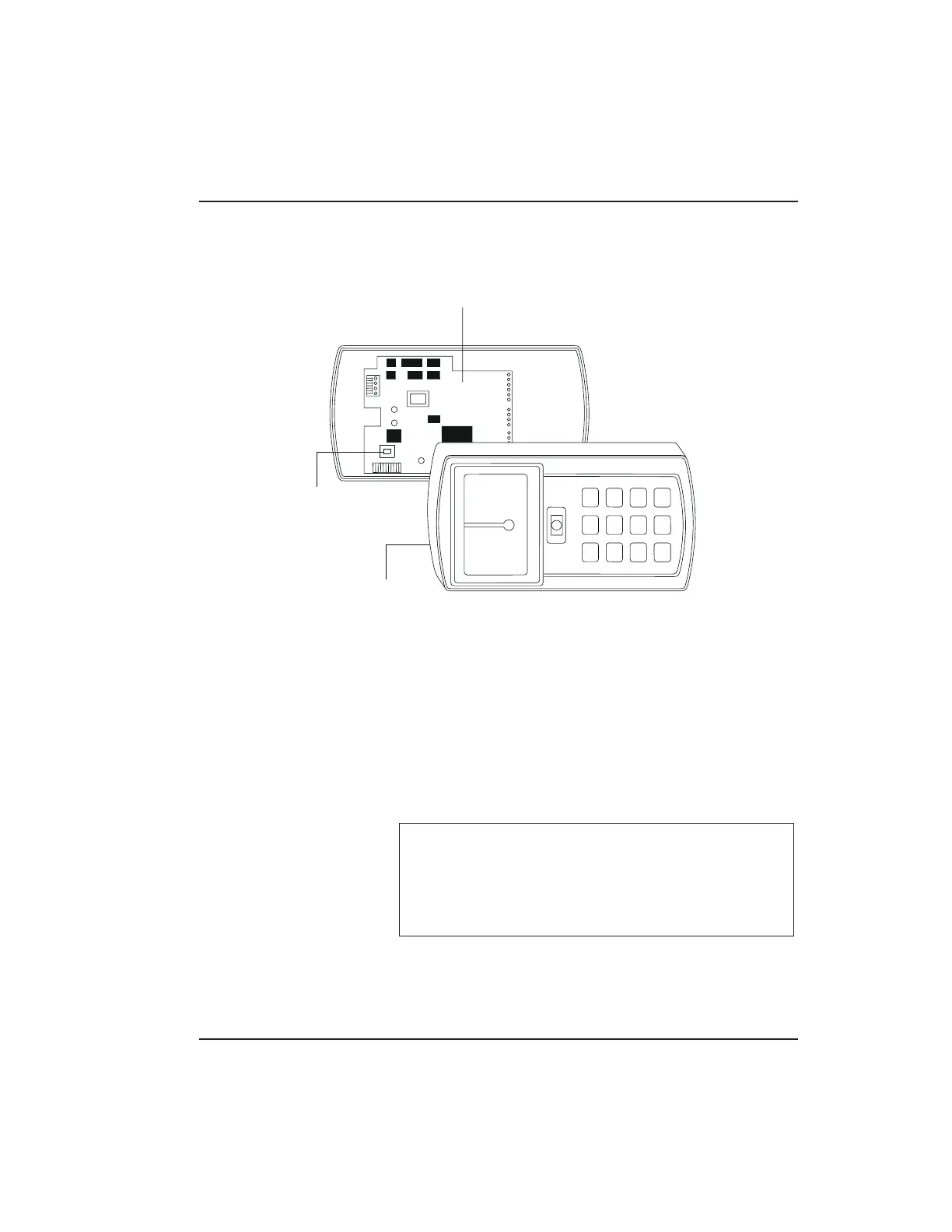
PCB
MASTER
CODE
SWITCH
(PROGRAM
SWITCH)
(ON REAR SIDE
OF PC BOARD)
CONTROLLER
Figure 2-7 Program Button Location on Main
Circuit Board
2.6 Defaulting prox.pad plus M emo ry Chapter 2: Installation
prox.pad plus Install/Program. Manual, PPP, D2 2-17