3.1.6 Wiring the Main
Relay
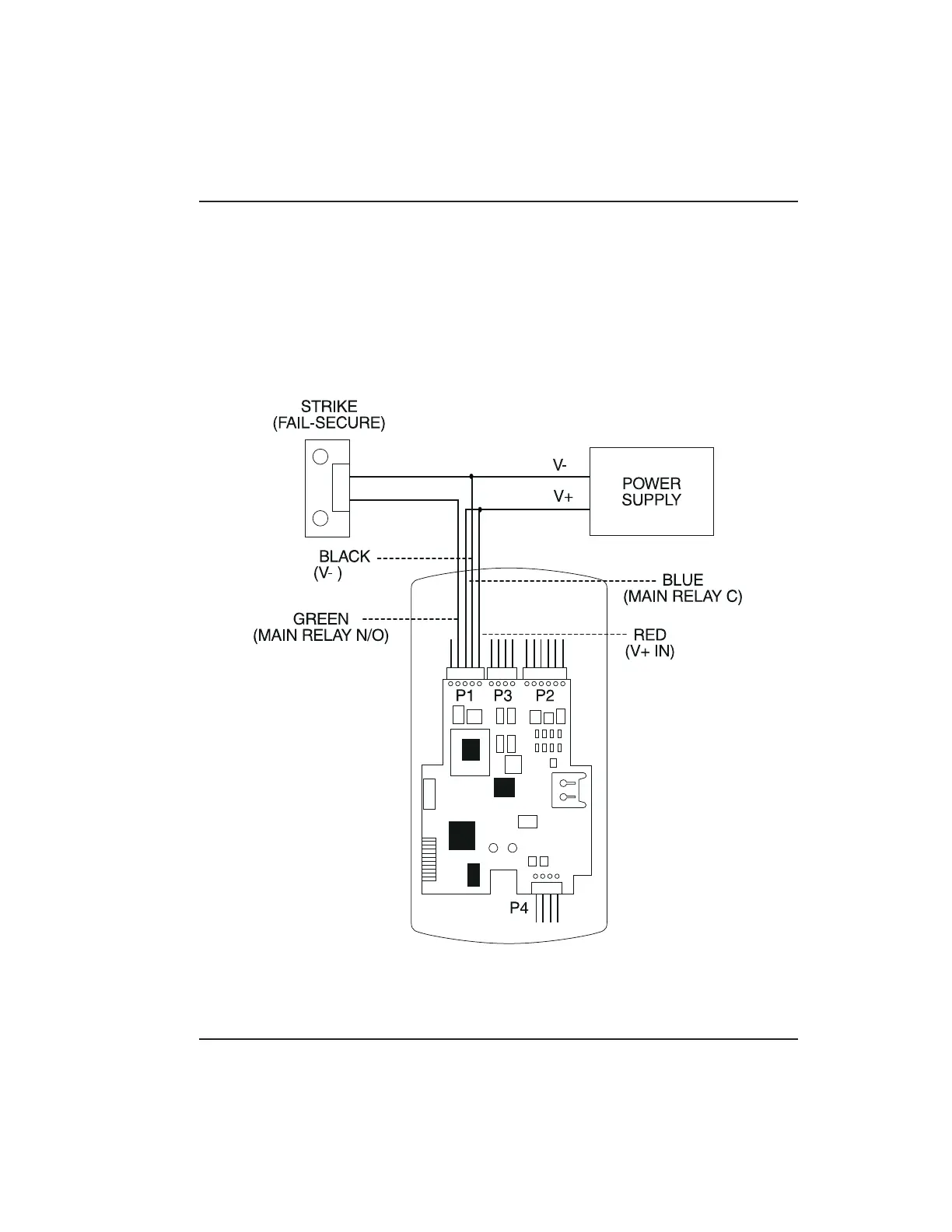
The door lock is wired to connector P1 on the prox.pad
plus main circuit board. Wiring for this 5-pin connector
is described in Table 2-2, Figure 3-6 provides an Electric
Strike (Fail Secure ) wiring diagram, Figure 3-7 a
MagLock (Fail Safe) wiring diagram. Refer to the
power supply recommendations in Table 1-1 if neces-
sary.
P5
Figure 3-6 Electric Strike (Fail Secure) Wiring
Diagram
3.1 Wiring the prox.pad plus Unit Chapter 3: Wiring
prox.pad plus Install/Program. Manual, PPP, D2 3-11