Product description
INTORQ | BA 14.0168 | 11/2018 18
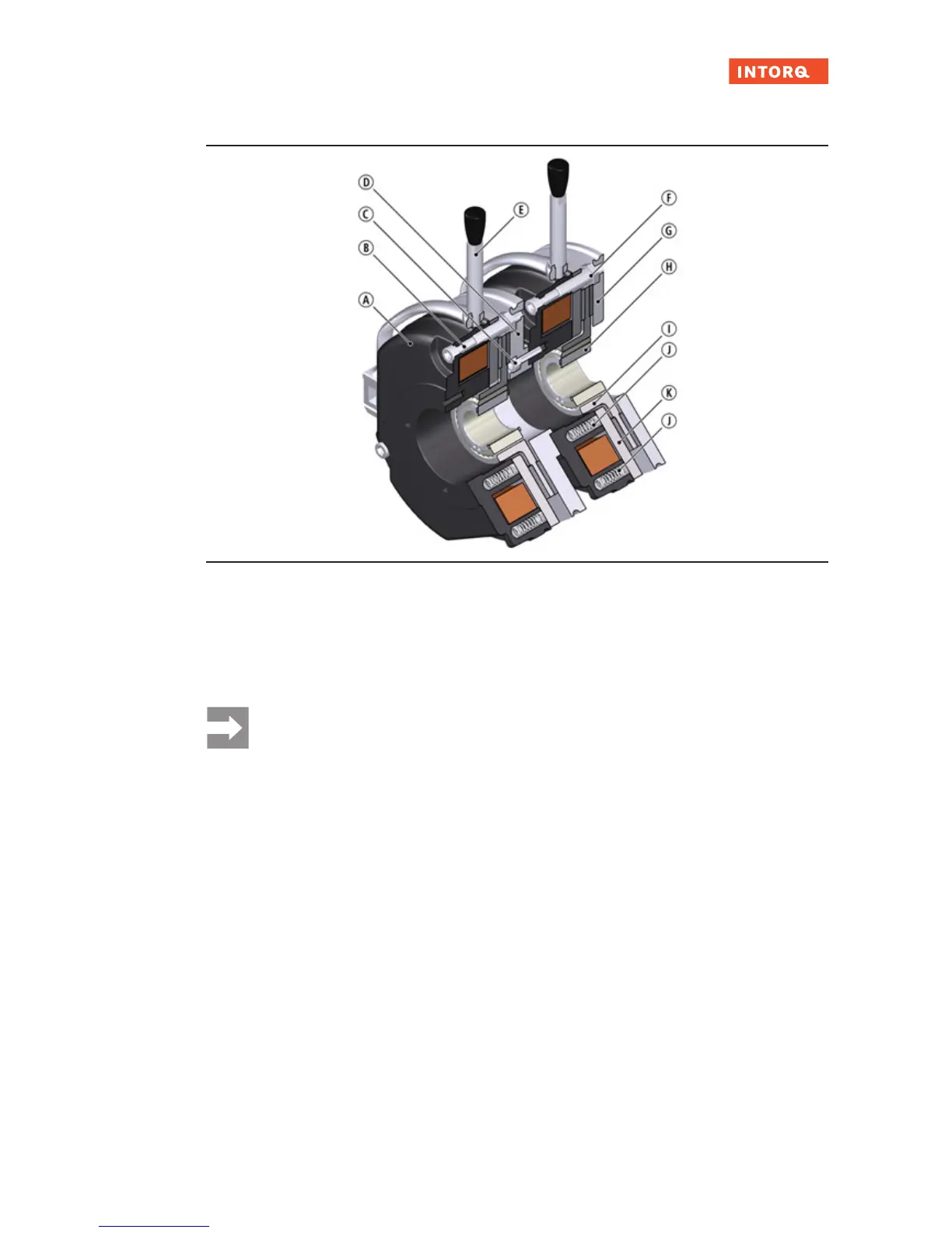
3.2.4 Double spring-applied brake
Fig.3: Design of the INTORQ BFK458 spring-applied brake: Basic module N, doubled design with intermediate flange
A
Stator
B
Socket head cap screw
C
Screw for intermediate flange
D
Intermediate flange
E
Hand-release (optional)
F
Sleeve bolt
G
Flange
H
Hub
I
Rotor
J
Pressure spring
K
Armature plate
Notice
A version of the double spring-applied brake using HFC (high-friction coefficient) linings is not
permitted.
3.3 Function
This brake is an electrically releasable spring-applied brake with a rotating brake disc (rotor) that is
equipped on both sides with friction linings. In its de-energised state, the rotor is clamped with braking
force applied by pressure springs between the armature plate and a counter friction surface. This corres-
ponds to a fail-safe functionality.
The brake torque applied to the rotor is transferred to the input shaft via a hub that has axial gear teeth.
The brake can be used as a holding brake, as an operating brake, and as an emergency stop brake for
high speeds.
The asbestos-free friction linings ensure a safe braking torque and low wear.
To release the brake, the armature plate is released electromagnetically from the rotor. The rotor, shifted
axially and balanced by the spring force, can rotate freely.