Mechanical installation
INTORQ | BA 14.0168 | 11/2018 42
5.7.2 Installing the flange (variants: size 06 - 16)
The flange can be screwed to the end shield on the outer hole circle (for screw dimensioning, refer to the
table Rated data: screw kit for brake assembly on separately screwed-on flange
,Page24).
NOTICE
Clearing holes for the screws in the end shield must be behind the threaded screw holes
in the flange. Without the clearing holes, the minimal rotor thickness cannot be used. The
screws must not press against the end shield.
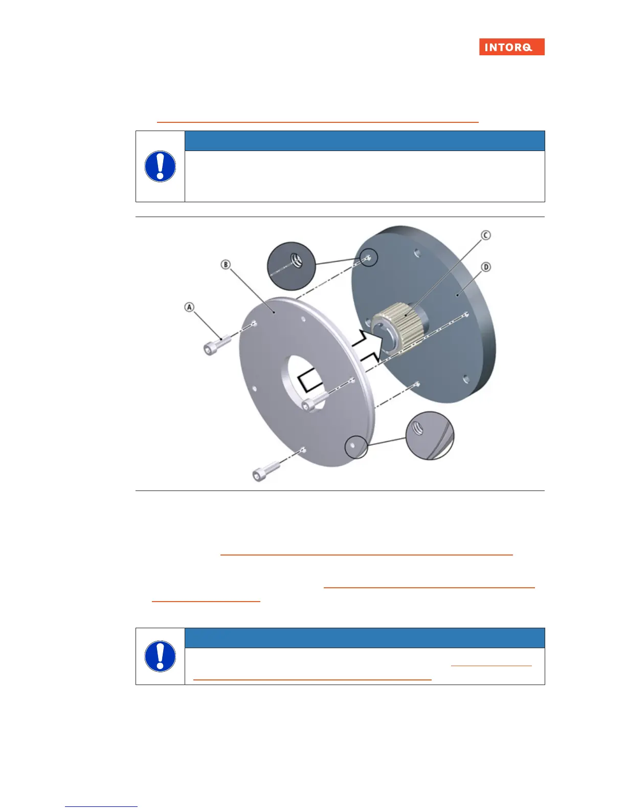
Fig.15: Flange mounting for sizes 06 - 16
A
Screw
1)
B
Flange
C
Hub
D
End shield
1)
According to the table Rated data: screw kit for brake assembly on separately screwed-on flange
,Page24
1. Make sure that there are clearing holes in the end shield at the positions of the screws in the stator
(for these free hole depths, refer to the table Rated data: screw kit for brake assembly on separately
screwed-on flange,Page24).
2. Place the flange against the end shield.
NOTICE
Tighten the screws evenly (for tightening torques, refer to the table Rated data: screw kit
for brake assembly on separately screwed-on flange,Page24 ).
3. Use the three screws to screw the flange to the end shield.