Mechanical installation
INTORQ | BA 14.0168 | 11/2018 46
Notice
Requirements:
¾
The first hub has to be mounted on the shaft!
¾
The first brake must be completely mounted!
¾
The air gap must be set!
1. Mount the intermediate flange with the four screws in the threads of the first magnet housing.
All other steps for mounting the second brake are carried out as described in the section Mounting the
brake,Page38.
NOTICE
With the double spring-applied brake design, when working with braking torques which are
greater than the standard braking torque, you need to check the screws connecting the
first brake. Please consult with INTORQ first!
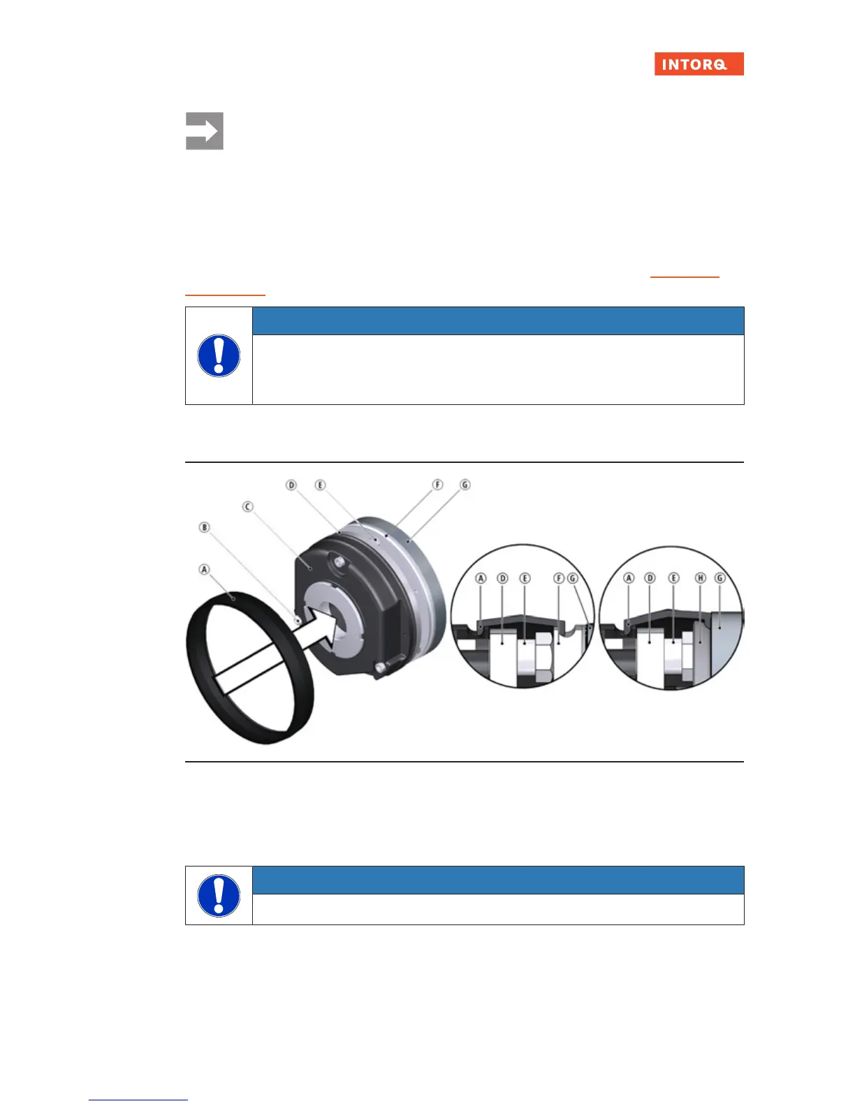
5.9 Cover ring assembly
Fig.19: Cover ring assembly
A
Cover ring
B
Socket head cap screw
C
Stator
D
Armature plate
E
Sleeve bolt
F
Flange
G
End shield
H
Friction plate
NOTICE
The cover ring may only be used in conjunction with a flange or friction plate!
1. Pull the cables through the cover ring.
2. Slide the cover ring over the stator.