Commissioning and operation
INTORQ | BA 14.0168 | 11/2018 61
¾
While current is being applied to the brake, make sure that the armature plate is completely tightened
and the drive moves without residual torque.
¾
Measure the DC voltage at the brake. Compare the measured DC voltage with the voltage indicated on
the name plate. The deviation must be less than ± 10%!
¾
When using bridge/half-wave rectifiers: After switching to one-way voltage, the measured DC voltage
may drop to 45% of the voltage specified on the name plate.
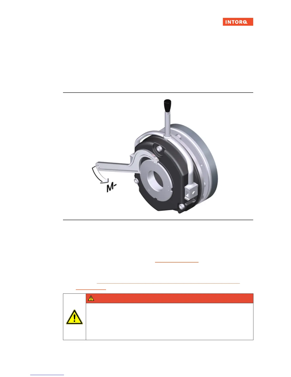
7.4.1 Brake torque reduction (for the optional adjustable braking torque)
Fig.33: Reducing the braking torque
1. Use a hook wrench to turn the torque adjustment ring counter-clockwise. This reduces the braking
torque.
– Note the correct position of the tappet notches on the torque adjustment ring: Only the latched-in
positions are permitted. It is forbidden to operate the brake when the notches are adjusted between
these latched-in positions! (Refer to chapter Brake torques
,Page21 for the values for the braking
torque reduction for each latched-in position.)
– Observe the max. permissible protrusion (h
Emax
) of the torque adjustment ring over the stator. (Refer
to the table Rated data for braking torques, depending on the speed and permissible limiting
speeds,Page23 for values of h
Emax
.)
DANGER
The reduction of the braking torque does not increase the maximum permissible air gap
s
Lmax
.
Do not change the hand-release setting for designs with hand-release.
Increasing the braking torque by screwing in the torque adjustment ring is only permitted
up to the default (as delivered) torque value .