Electrical installation
INTORQ | BA 14.0168 | 11/2018 55
6.8 Bridge/half-wave rectifier (optional)
BEG-561-□□□-□□□
The bridge-half-wave rectifiers are used to supply electromagnetic DC spring-applied brakes which are ap-
proved for use with such rectifiers. Other use is only permitted with the approval of INTORQ.
Once a set overexcitation period has elapsed, the bridge-half-wave rectifiers switch over from bridge recti-
fication to half-wave rectification.
Terminals 3 and 4 are in the DC circuit of the brake. The induction voltage peak for DC switching (refer to
the circuit diagram DC switching at the motor – fast engagement
,Page51) is limited by an integrated
overvoltage protection at terminals 5 and 6.
6.8.1 Assignment: Bridge/half-wave rectifier – brake size
Rectifier type Supply
voltage
Overexcitation Holding current reduction
Coil voltage Size Coil voltage Size
[V AC] [V DC] [V DC]
BEG-561-255-030
230 103
06 – 25
205
06 – 14
BEG-561-255-130 - 16 – 25
BEG-561-440-030-1 400 180 06 – 25 - -
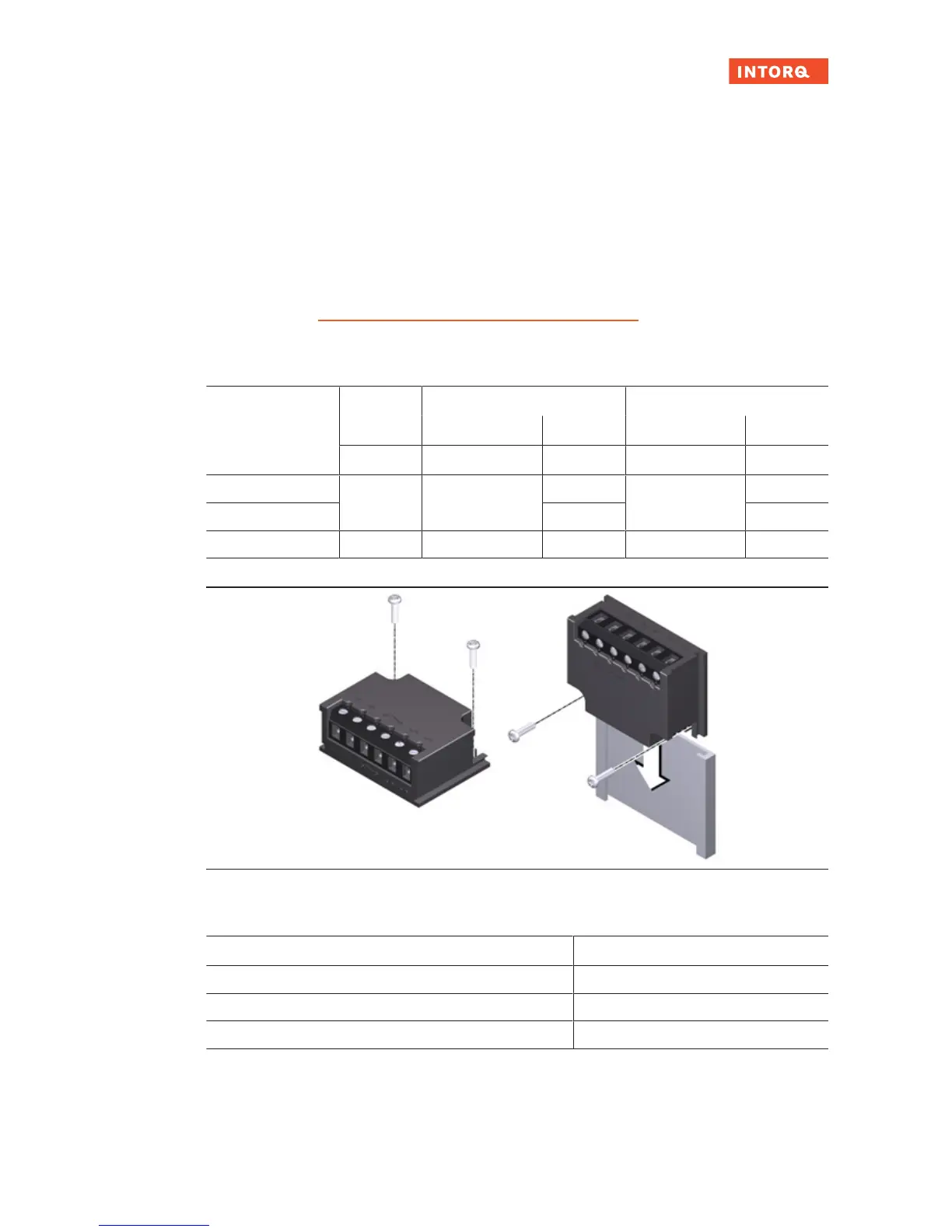
Fig.30: BEG-561 fastening options
6.8.2 Technical specifications
Rectifier type Bridge / half-wave rectifier
Output voltage for bridge rectification 0.9 x U
1
Output voltage for half-wave rectification 0.45 x U
1
Ambient temperature (storage/operation) [°C] -25 – +70
U
1
input voltage (40 - 60 Hz)