Electrical installation
INTORQ | BA 14.0168 | 11/2018 54
6.6 Minimum bending radius for the brake connection line
Size Wire cross-section Minimum bending radius
06
AWG 20
27.5 mm
08
10
12
14
16
18
45.6 mm20
25
Tab.13: Minimum bending radius for the brake connection cable
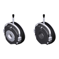
6.7 Technical specifications for the micro-switch
The brake can be equipped with a micro-switch for monitoring the release or wear. The micro-switch can
be integrated into the circuit as an NO or NC contact.
As of June 2012, a new small micro-switch (with UL acceptance) is in use, which is perfectly adapted to
the contour of the brake. The old switch design can be converted by connecting an adapter to the same
threaded holes.
Design Micro-switch
3-pole connecting cable
3 x 0.34 mm² (AWG22)
black / brown / blue
D = 4.8 mm, black, CSA
Style 2517/105°
Length: 1000 mm
Contacts Silver
Current carrying capacity 250 V AC Max. 3 A
Current carrying capacity 30 V DC Max. 3 A
Minimum load at 24 V DC 10 mA
Temperature range: -40 °C to +85 °C
Protection class IP67
Tab.14: Technical specifications for the micro-switch