Mechanical installation
INTORQ | BA 14.0168 | 11/2018 44
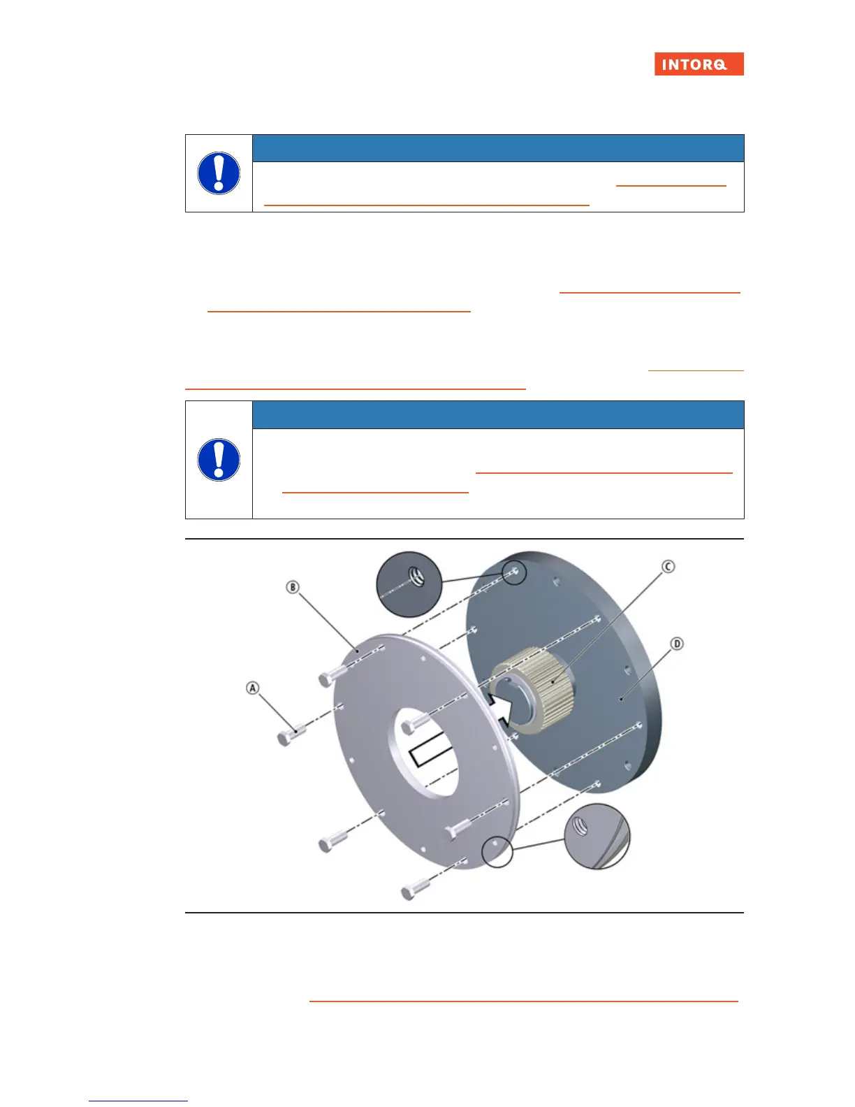
1. Place the flange against the end shield.
NOTICE
Tighten the screws evenly (for tightening torques, refer to the table Rated data: screw kit
for brake assembly on separately screwed-on flange,Page24 ).
2. Use the four screws to screw the flange to the end shield.
3. Check the height of the screw heads. The screw heads must not be higher than the minimum rotor
thickness. Use screws that comply with the information in the table Rated data: screw kit for brake as-
sembly on separately screwed-on flange,Page24.
5.7.4 Installing the flange (variants: size 25)
The flange can be screwed to the end shield onto the outer hole circle (refer to the table Rated data: screw
kit for brake assembly on separately screwed-on flange,Page24).
NOTICE
¾
Clearing holes for the screws in the end shield must be behind the threaded screw
holes in the flange (refer to the table Rated data: screw kit for brake assembly on sep-
arately screwed-on flange,Page24). Without the clearing holes, the minimal rotor
thickness cannot be used. The screws must not press against the end shield.
Fig.17: Flange mounting for size 25
A
Hex screw
1)
B
Flange
C
Hub
D
End shield
1)
According to the table Rated data: screw kit for brake assembly on separately screwed-on flange
,Page24