4. Power & Control Wiring
4.1. Connection Locations
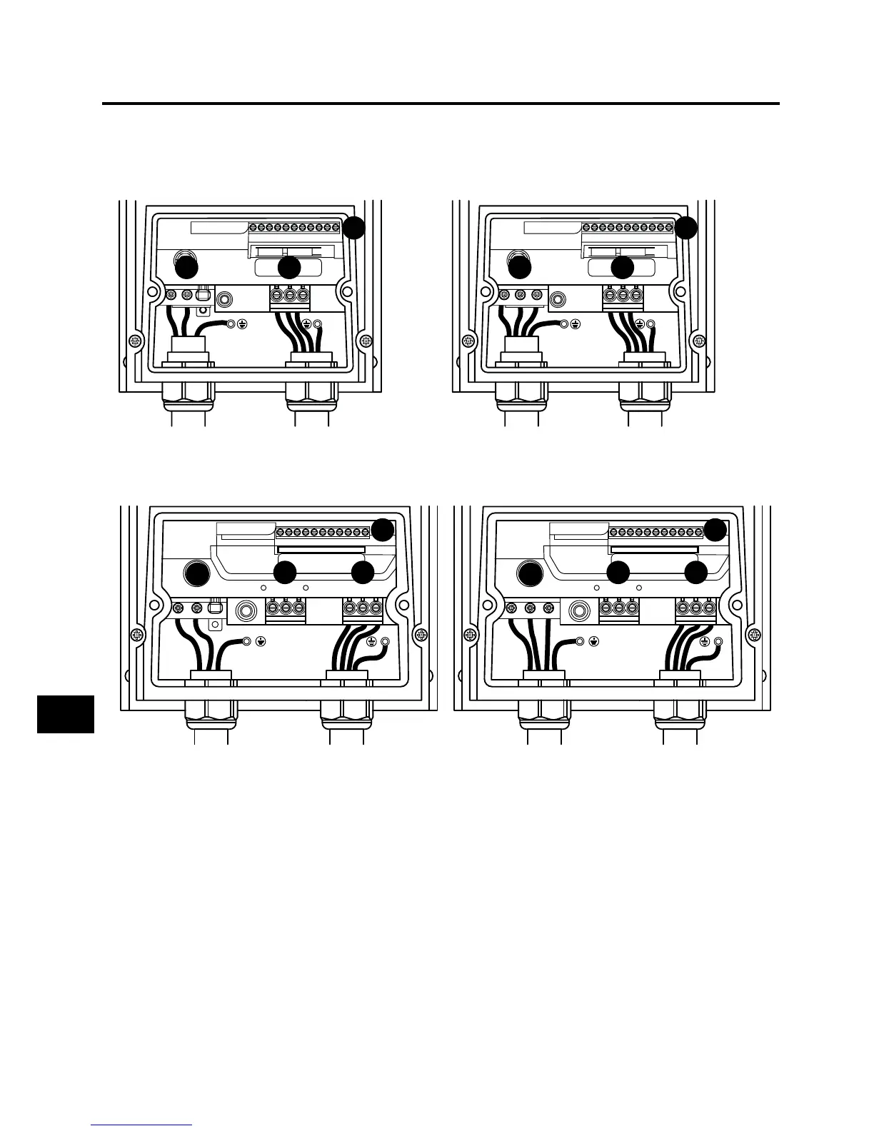
4.1.1. Connection locations – Frame size 1
Single phase supply 3 phase supply
L1
L3 EMCL2/N
UVW
1 2 3 4 5 6 7 8 9
10
11
I0I0I I0I0I
A
B
C
L1
L3 EMCL2/N
UVW
1 2 3 4 5 6 7 8 9
10
11
I0I0I I0I0I
A
B
C
4.1.2. Connection locations – Frame sizes 2, 3 and 4
Single phase supply 3 phase supply
L1
L3
EMC
L2/N
U V W
1 2 3 4 5 6 7 8 9
10
11
I0I0I I0I0I
BR
+
-
A
B
C
D
L1
L3
EMC
L2/N
U V W
1 2 3 4 5 6 7 8 9
10
11
I0I0I I0I0I
+
-
A
C
BR
D
B
A – Incoming Power Connections see section 4.4. Incoming Power Connection for more information
B – Motor Connections see section 4.5. Motor Connection for more information
C – Control Terminal Connections see section 4.10. Control Terminal Connections for more information
D – Brake Resistor see section 4.13. Optional Brake Resistor for more information
Power & Control Wiring
4