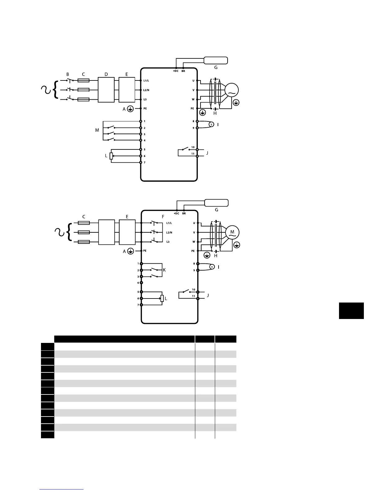
4.2. Connection Diagram
4.2.1. IP66 (Nema 4X) Non-Switched Units
4.2.2. IP66 (Nema 4X) Switched Units
Key Sec. Page
A Protective Earth (PE) Connection 4.3 12
B Incoming Power Connection 4.4 12
C Fuse / Circuit Breaker Selection 4.4.2 12
D Optional Input Choke 4.4.3 13
E Optional External EMC Filter 4 .10 17
F Internal Disconnect / Isolator 4.3 14
G Optional Brake Resistor 4 .13 16
H Motor Connection
I Analog Output 4.10.1 15
J Relay Output 4.10.2 15
K Using the REV/0/FWD Selector Switch (Switched Version Only) 4.8 14
L Analog Inputs 4.10.3 15
M Digital Inputs 4.10.4 16
M
D
Power & Control Wiring
4