4.7. Control Terminal Wiring
All analog signal cables should be suitably shielded. Twisted pair cables are recommended.
Power and Control Signal cables should be routed separately where possible, and must not be routed parallel to each other.
Signal levels of different voltages e.g. 24 Volt DC and 110 Volt AC, should not be routed in the same cable.
Maximum control terminal tightening torque is 0.5Nm.
Control Cable entry conductor size: 0.05 – 2.5mm2 / 30 – 12 AWG.
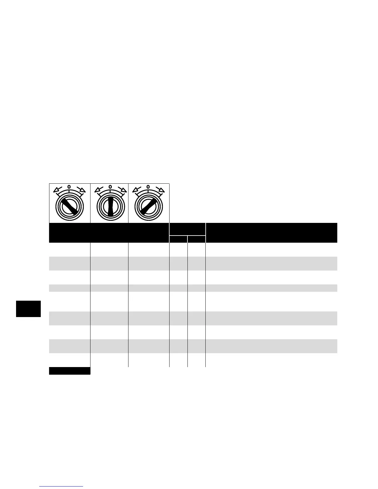
4.8. Using the REV/0/FWD Selector Switch (Switched Version Only)
By adjusting the parameter settings the Optidrive can be configured for multiple applications and not just for Forward or Reverse.
This could typically be for Hand/Off/Auto applications (also known and Local/Remote) for HVAC and pumping industries.
The integrated switch operates in parallel with drive terminal 2 (T2) and terminal 3 (T3) as digital input 1 and digital input 2.
By default, the integrated switch is enabled.
If required, the built in control switch may be disabled using the following method:
1) Set correct value in P-14 to enable advanced parameter access, e.g. 201
2) Go to “P-00” and make sure drive is in stop condition (not running, not tripped).
3) Press and hold “STOP” button for about 1s, drive will show “Lc-OFF” or “Lc-On” message.
4) Use “UP” or “DOWN” key to select the option: “Lc-OFF” means integrated switches are enabled. “Lc-On” means the switches are
locked/disabled.
5) Press the “STOP” button again to exit.
Switch Position
Parameters
to Set
Notes
P-12 P-15
Run Reverse STOP Run Forward 0 0
Factory Default Configuration
Run Forward or Reverse with speed controlled from the Local POT
STOP STOP Run Forward 0 5,7
Run forward with speed controlled form the local POT
Run Reverse – Disabled
Preset Speed 1 STOP Run Forward 0 1
Run Forward with speed controlled from the Local POT
Preset Speed 1 provides a ‘Jog’ Speed set in P-20
Run Reverse STOP Run Forward 0 6, 8 Run Forward or Reverse with speed controlled from the Local POT
Run in Auto STOP Run in Hand 0 4
Run in Hand – Speed controlled from the Local POT
Run in Auto – Speed controlled using Analog input 2 e.g. from
PLC with 4-20mA signal.
Run in Speed
Control
STOP Run in PI Control 5 1
In Speed Control the speed is controlled from the Local POT
In PI Control, Local POT controls PI set point
Run in Preset
Speed Control
STOP Run in PI Control 5
0, 2, 4,
5, 8..12
In Preset Speed Control, P-20 sets the Preset Speed
In PI Control, POT can control the PI set point (P-44=1)
Run in Hand STOP Run in Auto 3 6
Hand – Speed controlled from the Local POT
Auto – Speed Reference from Modbus
Run in Hand STOP Run in Auto 3 3
Hand – Speed reference from Preset Speed 1 (P-20)
Auto – Speed Reference from Modbus
NOTE To be able to adjust parameter P-15, extended menu access must be set in P-14 (default value is 101)
Power & Control Wiring
4