Low Frequency Torque Boost is used to increase the applied motor voltage and hence current at low output frequencies. This can
improve low speed and starting torque. Increasing the boost level will increase motor current at low speed, which may result in the
motor temperature rising - force ventilation or additional cooling of the motor may then be required. In general, the lower the motor
power, the higher the boost setting that may be safely used.
For IM motor types (P-51 = 0 or 1), the value entered determines the voltage applied to the motor at 0.0Hz relative to P-07 setting. e.g.
P-07 = 400V
P-11 = 2%
Output voltage applied to the motor at 0.0Hz = 2% x 400V = 8V.
This boost voltage is then linearly reduced up to 50% of the motor rated speed (P-09).
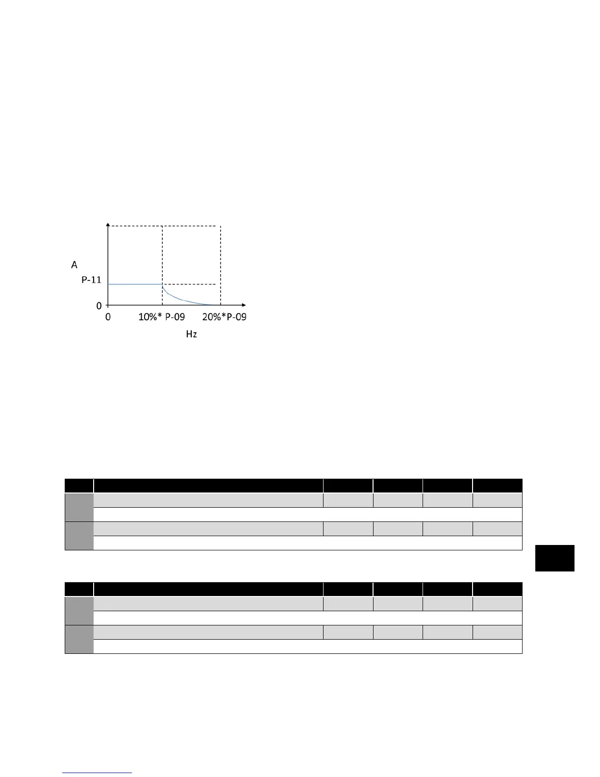
When operating with alternative motor types (P-51 = 2, 3 or 4) this parameter is used to set an additional boost current which is
injected into the motor. The actual current level is defined as 4*P-11*P-08.
This additional current is injected between 0.0Hz and 10% of rated frequency. Above this point, the boost current is reduced
according to the diagram below.
Speed Limits (relevant parameters)
These parameters define the range of output frequency and therefore the speed range through which the drive will operate.
As described above:
If P-10 = 0, Values are Hz
If P-10 <> 0, Values are RPM
Dependent on the speed reference selection, the operation will be as follows:
For Analog Speed Reference: Applying 0% analog signal results in the speed reference of P-02. Applying 100% signal results in the
speed reference of P-01. Scaling between these points is linear as shown below.
Scaling may be adjusted on Analog Input 1 only using the AI1 Scaling & Offset function shown on page 25.
The value used for the speed reference:
Par. Description Minimum
Maximum
Default Units
P-01 Maximum Frequency / Speed Limit P-02 500.0
50.0 (60.0)
Hz / RPM
Maximum output frequency or motor speed limit – Hz or RPM. If P-10 >0, the value entered / displayed is in RPM.
P-02 Minimum Frequency / Speed Limit 0.0 P-01 20.0 Hz / RPM
Minimum speed limit – Hz or RPM. If P-10 >0, the value entered / displayed is in RPM.
Acceleration and Deceleration (relevant parameters)
Par. Description Minimum
Maximum
Default Units
P-03 Acceleration Ramp Time 0.00 600.0 5.0 s
Acceleration ramp time from zero Hz / RPM to base frequency (P-09) in seconds.
P-04 Deceleration Ramp Time 0.00 600.0 5.0 s
Deceleration ramp time from base frequency (P-09) to standstill in seconds. When set to 0.00, the value of P-24 is used.
Parameters
6