The Fire Mode function is designed to ensure continuous operation of the drive in emergency conditions until the drive is no longer
capable of sustaining operation. The Fire Mode input may be a normally open (Close to Activate Fire Mode) or Normally Closed
(Open to Activate Fire Mode) according to the setting of P-30 Index 2. In addition, the input may be momentary or maintained type,
selected by P-30 Index 3.
This input may be linked to a fire control system to allow maintained operation in emergency conditions, e.g. to clear smoke or
maintain air quality within that building.
The fire mode function is enabled when P-15 = 15, 16, 17 or 18, with Digital Input 3 assigned to activate fire mode.
Fire Mode disables the following protection features in the drive:
O-t Heat-sink Over-Temperature
U-t Drive Under Temperature
Th-FLt Faulty Thermistor on Heat-sink
E-trip External Trip
4-20 F 4-20mA fault
Ph-Ib Phase Imbalance
P-Loss Input Phase Loss Trip
SC-trp Communications Loss Trip
It-trp Accumulated overload Trip
Out-F Drive output fault, Output stage trip
The following faults will result in a drive trip, auto reset and restart:
O-Volt Over Voltage on DC Bus
U-Volt Under Voltage on DC Bus
h O-I Fast Over-current Trip
O-I Instantaneous over current on drive output
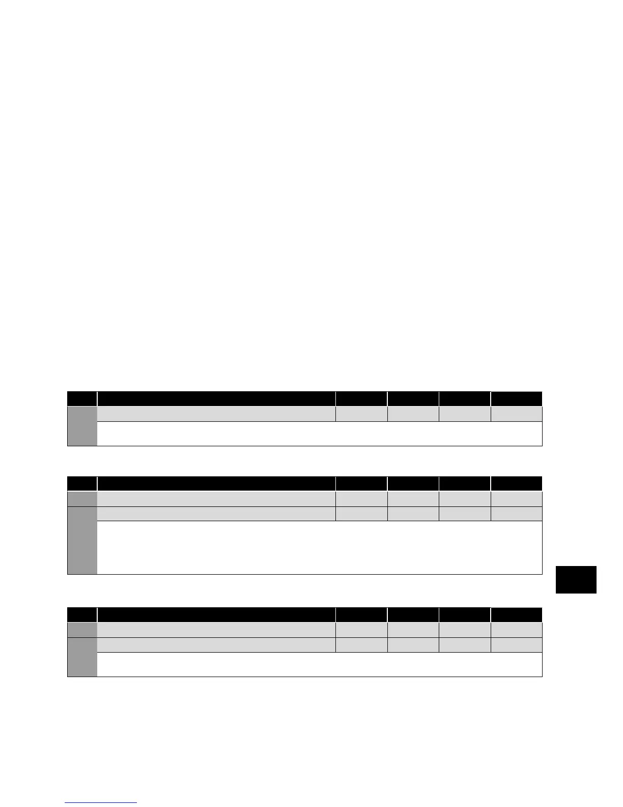
Switching Frequency Selection (relevant parameters)
Par. Description Minimum
Maximum
Default Units
P-17 Maximum Effective Switching Frequency 4 32 8 kHz
Sets maximum effective switching frequency of the drive. If “rEd” is displayed when the parameter is viewed, the switching frequency has
been reduced to the level in P00-32 due to excessive drive heatsink temperature.
Skip Frequency (relevant parameters)
Par. Description Minimum
Maximum
Default Units
P-26 Skip Frequency Hysteresis Band 0.0 P-01 0.0 Hz / RPM
P-27 Skip Frequency Centre Point 0.0 P-01 0.0 Hz / RPM
The Skip Frequency function is used to avoid the Optidrive operating at a certain output frequency, for example at a frequency which
causes mechanical resonance in a particular machine. Parameter P-27 defines the centre point of the skip frequency band, and is used in
conjunction with P-26. The Optidrive output frequency will ramp through the defined band at the rates set in P-03 and P-04 respectively,
and will not hold any output frequency within the defined band. If the frequency reference applied to the drive is within the band, the
Optidrive output frequency will remain at the upper or lower limit of the band.
V/F Characteristic Adjustment (relevant parameters)
Par. Description Minimum
Maximum
Default Units
P-28 V/F Characteristic Adjustment Voltage 0 P-07 0 V
P-29 V/F Characteristic Adjustment Voltage 0.0 P-09 0.0 Hz
This parameter in conjunction with P-28 sets a frequency point at which the voltage set in P-29 is applied to the motor. Care must be taken
to avoid overheating and damaging the motor when using this feature.
Parameters
6