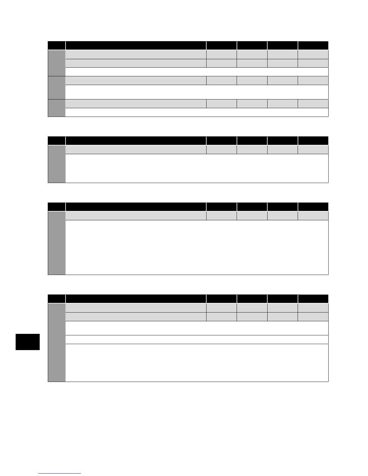
DC Injection Braking (relevant parameters)
Par. Description Minimum
Maximum
Default Units
P-32 Index 1: Duration 0.0 25.0 0.0 s
Index 2: DC Injection Mode 0 2 0 -
Determined by Autotune, adjustment is not normally required.
P-58 DC Injection Speed 0.0 P-01 0.0 Hz / RPM
Sets the speed at which DC injection current is applied during braking to Stop, allowing DC to be injected before the drive reaches zero
speed if desired.
P-59 DC Injection Current 0.0 100.0 20.0 %
Sets the level of DC injection braking current applied according to the conditions set in P-32 and P-58.
Spin Start (relevant parameters)
Par. Description Minimum
Maximum
Default Units
P-33 Spin Start 0 2 0 -
0: Disabled
1: Enabled. When enabled, on start up the drive will attempt to determine if the motor is already rotating, and will begin to control the
motor from its current speed. A short delay may be observed when starting motors which are not turning.
2: Enabled on Trip, Brown Out or Coast Stop. Spin start is only activated following the events listed, otherwise it is disabled.
Dynamic braking (relevant parameters)
Par. Description Minimum
Maximum
Default Units
P-34 Brake Chopper Enable (Not Size 1) 0 4 0 -
0: Disabled
1: Enabled With Software Protection. Brake chopper enabled with software protection for a 200W continuous rated resistor.
2: Enabled Without Software Protection. Enables the internal brake chopper without software protection. An external thermal
protection device should be fitted.
3: Enabled With Software Protection. As setting 1, however the Brake Chopper is only enabled during a change of the
frequency setpoint, and is disabled during constant speed operation.
4: Enabled Without Software Protection. As setting 2, however the Brake Chopper is only enabled during a change of the
frequency setpoint, and is disabled during constant speed operation.
Display Scaling (relevant parameters)
Par. Description Minimum
Maximum
Default Units
P-40 Index 1: Display Scaling Factor 0.000 16.000 0.000 -
Index 2: Display Scaling Source 0 3 0 -
Allows the user to program the Optidrive to display an alternative output unit scaled from either output frequency (Hz), Motor Speed
(RPM) or the signal level of PI feedback when operating in PI Mode.
Index 1: Used to set the scaling multiplier. The chosen source value is multiplied by this factor.
Index 2: Defines the scaling source as follows:
0: Motor Speed. Scaling is applied to the output frequency if P-10 = 0, or motor RPM if P-10 > 0.
1: Motor Current. Scaling is applied to the motor current value (Amps).
2: Analog Input 2 Signal Level. Scaling is applied to analog input 2 signal level, internally represented as 0 – 100.0%.
3: PI Feedback. Scaling is applied to the PI feedback selected by P-46, internally represented as 0 – 100.0%.
Parameters
6