Low speed and starting of the motor may be further optimised by adjusting P-11.
o In PM motor control mode, P-11 adjust the additional current injected into the motor at low frequency to help maintain the rotor
alignment and ensure reliable starting.
Speed regulation and response to load changes may be improved by adjusting P-11 Vector Gain to suit the motor and connected
load.
o Higher values will provide a more dynamic behaviour at the risk of instability.
Synchronous Reluctance Motors (SynRM)
Suitable Motors
Optidrive E3 provides open loop control of synchronous reluctance AC motors, intended to allow the use of high effciency motors in
simple applications.
Commissioning Procedure
When operating with synchronous reluctance motors, the commissioning steps are as follows:
Enter the motor rated voltage in parameter P-07.
Enter the Motor Rated Current in P-08.
Enter the motor rated frequency in P-09.
Optionally enter the motor rated speed in P-10.
Enabled Advanced Parameter Access by setting P-14 = P-37 + 100 (Default : 201).
Select SynRM motor control in by setting P-51 = 4.
Carry out an Autotune.
o For SynRM motor operation, an Autotune MUST be carried out.
o This is achieved by setting P-52 = 1.
o The autotune will begin IMMEDIATELY following the setting of this parameter!
o The drive output will be enabled, and the motor shaft may move. It is important to ensure this is safe before carrying out the
autotune.
o For SynRM motors, the autotune measures the motor data required for correct operation.
It should now be possible to operate the motor.
Low speed and starting of the motor may be further optimised by adjusting P-11.
o In SynRM motor control mode, P-11 adjust the additional current injected into the motor at low frequency to help maintain the
rotor alignment and ensure reliable starting.
Speed regulation and response to load changes may be improved by adjusting P-11 or P-53 to suit the motor and connected
load.
o Higher values will provide a more dynamic behaviour at the risk of instability.
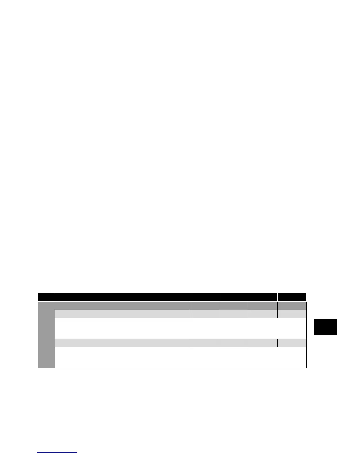
Overload Management (relevant parameters)
Par. Description Minimum
Maximum
Default Units
P-60 Motor Overload Management - - - -
Index 1: Thermal Overload Retention 0 1 0 1
0: Disabled
1: Enabled. When enabled, the drive calculated motor overload protection information is retained after the mains power is removed
from the drive.
Index 2: Thermal Overload Limit Reaction 0 1 0 1
0: It.trp. When the overload accumulator reaches the limit, the drive will trip on It.trp to prevent damage to the motor.
1: Current Limit Reduction. When the overload accumulator reaches 90% of, the output current limit is internally reduced to 1
00% of
P-08 in order to avoid an It.trp. The current limit will return to the setting in P-54 when the overload accumulator reaches 10%.
Parameters
6