OptidriveODP‐2UserGuideRevisions1.30
36
www.invertekdrives.com
8ExtendedParameters
8. ExtendedParameters
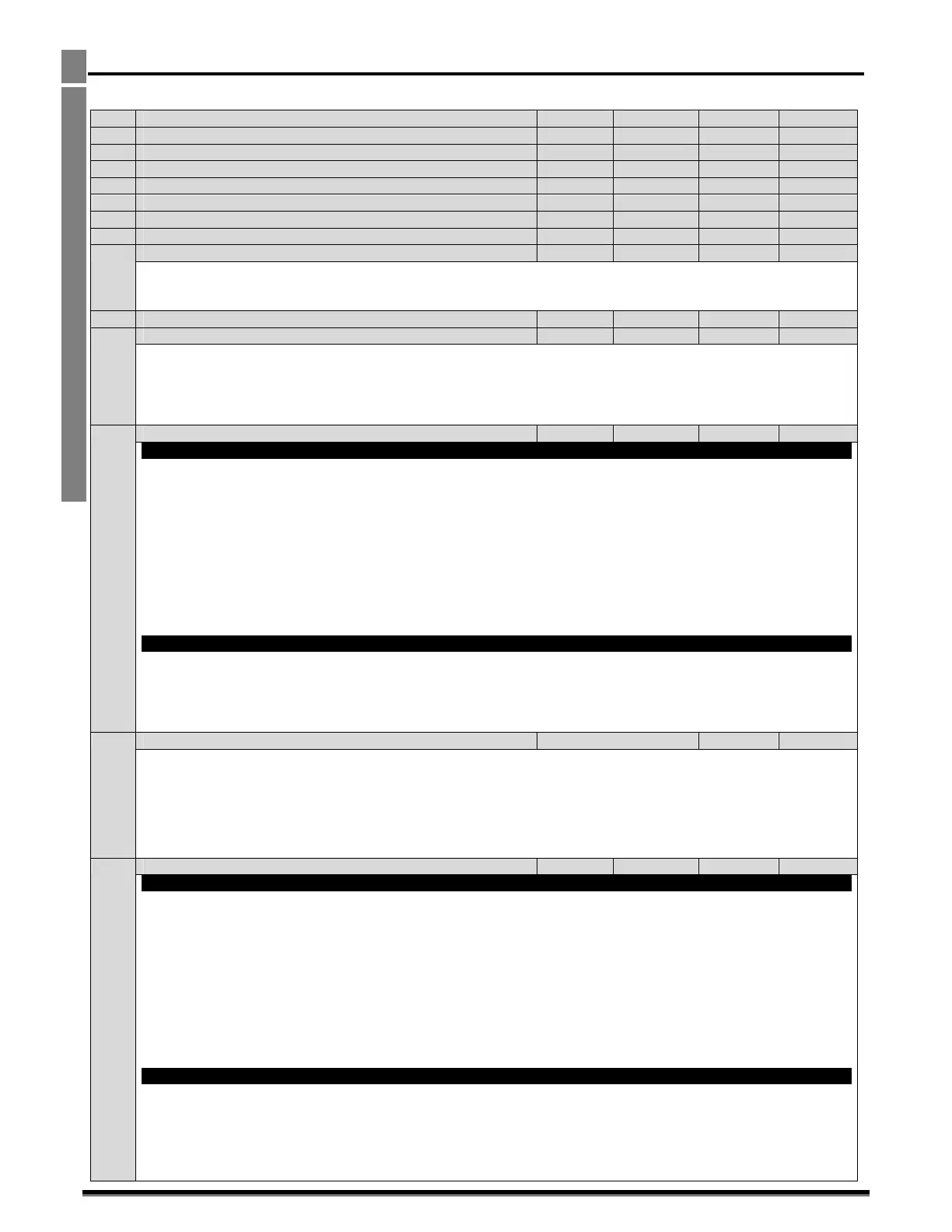
8.1. ParameterGroup2‐Extendedparameters
Par ParameterName Minimum Maximum Default Units
P2‐01 Preset/JogFrequency/Speed1 P1‐02 P1‐01 5.0 Hz/Rpm
P2‐02 Preset/JogFrequency/Speed2 P1‐02 P1‐01 10.0 Hz/Rpm
P2‐03 Preset/JogFrequency/Speed3 P1‐02 P1‐01 25.0 Hz/Rpm
P2‐04 Preset/JogFrequency/Speed4 P1‐02 P1‐01 50.0(60.0) Hz/Rpm
P2‐05 Preset/JogFrequency/Speed5 P1‐02 P1‐01 0.0 Hz/Rpm
P2‐06 Preset/JogFrequency/Speed6 P1‐02 P1‐01 0.0 Hz/Rpm
P2‐07 Preset/JogFrequency/Speed7 P1‐02 P1‐01 0.0 Hz/Rpm
P2‐08 Preset/JogFrequency/Speed8 P1‐02 P1‐01 0.0 Hz/Rpm
PresetSpeeds/FrequenciesselectedbydigitalinputsdependingonthesettingofP1‐13.
IfP1‐10=0,thevaluesareenteredasHz.IfP1‐10>0,thevaluesareenteredasRpm.
Settinganegativevaluewillreversethedirectionofmotorrotation.
P2‐09 SkipFrequencyCentrePoint P1‐02 P1‐01 0.0 Hz/Rpm
P2‐10 SkipFrequencyBandWidth 0.0 P1‐01 0.0 Hz/Rpm
TheSkipFrequencyfunctionisusedtoavoidtheOptidriveoperatingatacertainoutputfrequency,forexampleatafrequency
whichcausesmechanicalresonanceinaparticularmachine.ParameterP2‐09definesthecentrepointoftheskipfrequencyband,
andisusedconjunctionwithP2‐10.TheOptidriveoutputfreque
ncywillrampthroughthedefinedbandattheratessetinP1‐03
andP1‐04respectively,andwillnotholdanyoutputfrequencywithinthedefinedband.Ifthefrequencyreferenceappliedtothe
driveiswithintheband,theOptidriveoutputfrequencywillremainattheupperorlo
werlimitoftheband.
P2‐11 AnalogOutput1(Terminal8)FunctionSelect 0 11 8 ‐
DigitalOutputMode.Logic1=+24VDC
0:DriveEnabled(Running).Logic1whentheOptidriveisenabled(Running)
1:DriveHealthy.Logic1WhennoFaultconditionexistsonthedrive
2:AtTargetFrequency(Speed).Logic1whentheoutputfrequencymatchesthesetpointfrequency
3:OutputFre
quency>0.0.Logic1whenthemotorrunsabovezerospeed
4:OutputFrequency>=Limit.Logic1whenthemotorspeedexceedstheadjustablelimit
5:OutputCurrent>=Limit.Logic1whenthemotorcurrentexceedstheadjustablelimit
6:MotorTorque>=Limit.Lo
gicwhenthemotortorqueexceedstheadjustablelimit
7:AnalogInput2SignalLevel>=Limit.LogicwhenthesignalappliedtotheAnalogInput2exceedstheadjustablelimit
Note:Whenusingsettings4–7,parametersP2‐16andP2‐17mus
tbeusedtogethertocontrolthebehaviour.Theoutputwill
switchtoLogic1whentheselectedsignalexceedsthevalueprogrammedinP2‐16,andreturntoLogic0whenthesignalfalls
belowthevalueprogrammedinP2‐17.
AnalogOutputMode
8:OutputFrequency(MotorSpeed).0toP‐01
9:Output(Motor)Current.0to200%ofP1‐08
10:MotorTorque.0to200%ofmotorratedtorque
11:Output(Motor)Power.0to150%ofdriveratedpower
12:PIDOutput.Outpu
tfromtheinternalPIDController,0–100%
P2‐12 AnalogOutput1(Terminal8)Format SeeBelow
U 0-10
‐
U 0-10 =0to10V.
U 10-0=10to0V,
A 0-20=0to20mA
A 20-0=20to0mA
A 4-20
=4to20mA
A 20-4=20to4mA
P2‐13 AnalogOutput2(Terminal11)FunctionSelect 0 11 9 ‐
DigitalOutputMode.Logic1=+24VDC
0:DriveEnabled(Running).Logic1whentheOptidriveisenabled(Running)
1:DriveHealthy.Logic1WhennoFaultconditionexistsonthedrive
2:AtTargetFrequency(Speed).Logic1whentheoutputfrequencymatchesthesetpointfrequency
3:OutputFre
quency>0.0.Logic1whenthemotorrunsabovezerospeed
4:OutputFrequency>=Limit.Logic1whenthemotorspeedexceedstheadjustablelimit
5:OutputCurrent>=Limit.Logic1whenthemotorcurrentexceedstheadjustablelimit
6:OutputTo
que>=Limit.Logicwhenthemotortorqueexceedstheadjustablelimit
7:AnalogInput2SignalLevel>=Limit.LogicwhenthesignalappliedtotheAnalogInput2exceedstheadjustablelimit
Note:Whenusingsettings4–7,parametersP2‐16andP2‐17mus
tbeusedtogethertocontrolthebehaviour.Theoutputwill
switchtoLogic1whentheselectedsignalexceedsthevalueprogrammedinP2‐16,andreturntoLogic0whenthesignalfalls
belowthevalueprogrammedinP2‐17.
AnalogOutputMode
8:OutputFrequency(MotorSpeed).0toP‐01
9:Output(Motor)Current.0to200%ofP1‐08
10:MotorTorque.0to200%ofmotorratedtorque
11:Output(Motor)Power.0to150%ofdriveratedpower
12:PIDOutput.Outpu
tfromtheinternalPIDController,0–100%

 Loading...
