OptidriveODP‐2UserGuideRevision1.30
www.invertekdrives.com
15
3 MechanicalInstallation
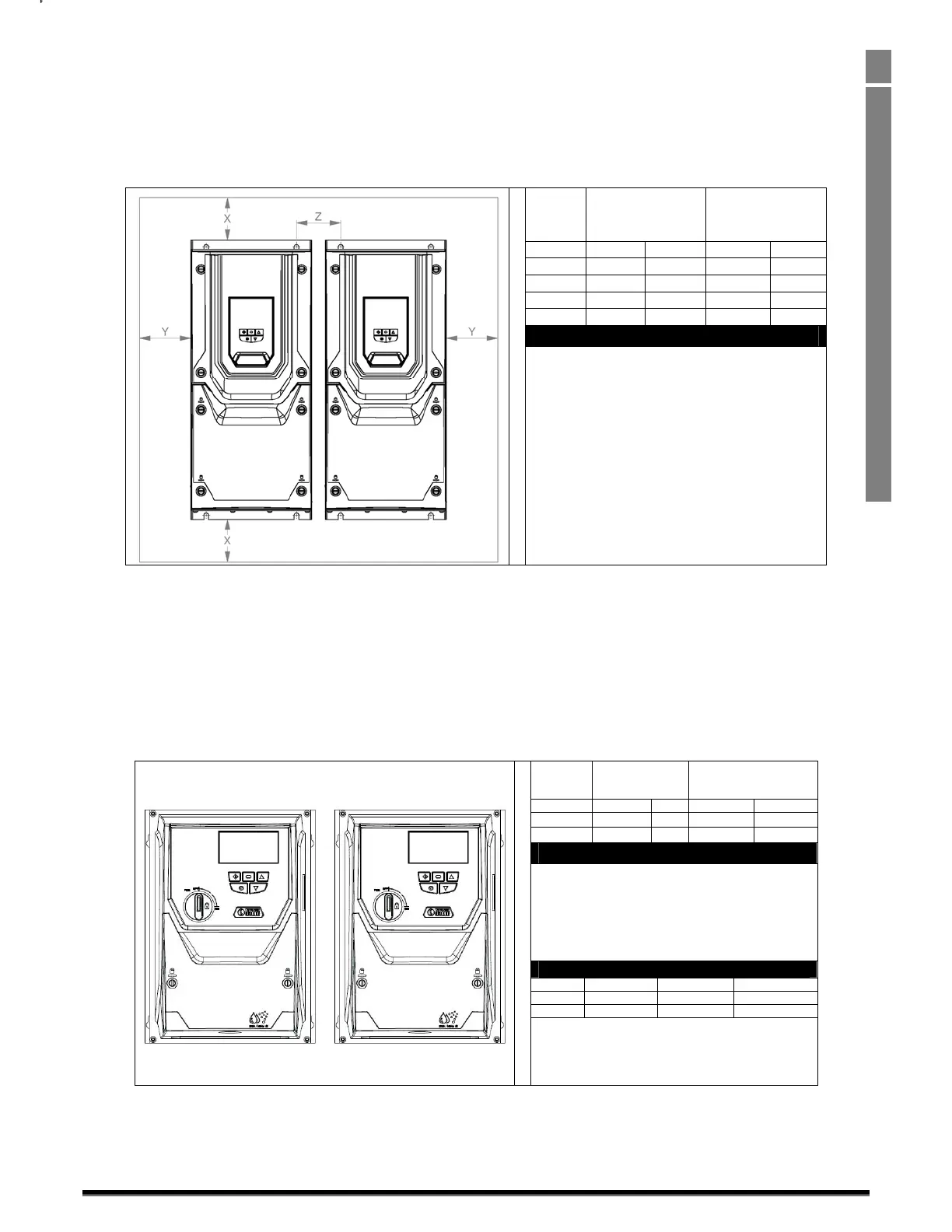
3.7. Guidelinesformounting(IP55Units)
• Beforemountingthedrive,ensurethatthechosenlocationmeetstheenvironmentalconditionrequirementsforthedriveshownin
section10.1
• Thedrivemustbemountedvertically,onasuitableflatsurface
• Theminimummountingclearancesasshowninthetablebelowmustbeobserved
• Themountingsi
teandchosenmountingsshouldbesufficienttosupporttheweightofthedrives
• IP55unitsdonotrequiremountinginsideanelectricalcontrolcabinet;howevertheymaybeifdesired.
Drive
Size
X
Above&
Below
Y
Either
Side
mm in mm in
4
200 7.87 10 0.39
5
200 7.87 10 0.39
6
200 7.87 10 0.39
7
200 7.87 10 0.39
Note:
Typicaldriveheatlossesareapproximately3%of
operatingloadconditions.
Aboveareguidelinesonlyandtheoperatingambient
temperatureofthedriveMUSTbemaintainedatall
times.
• Usingthedriveasatemplate,orthedimensionsshownabove,markthelocationsrequiredfordrilling
• SuitablecableglandstomaintaintheIPprotectionofthedrivearerequired.Glandsizesshouldbeselectedbasedonthenumberand
sizeoftherequiredconnectioncables.Drivesaresuppliedwi
thaplain,undrilledglandplatetoallowthecorrectholesizestobecut
asrequired.Removetheglandplatefromthedrivepriortodrilling.
3.8. Guidelinesformounting(IP66Units)
• Beforemountingthedrive,ensurethatthechosenlocationmeetstheenvironmentalconditionrequirementsforthedriveshownin
section10.1
• Thedrivemustbemountedvertically,onasuitableflatsurface
• Theminimummountingclearancesasshowninthetablebelowmustbeobserved
• Themountingsi
teandchosenmountingsshouldbesufficienttosupporttheweightofthedrives
Y
X
X
Drive
Size
X
Above&
Below
Y
Either
Side
mm in mm in
2
200 7.87 10 0.39
3
200 7.87 10 0.39
Note:
Typicaldriveheatlossesareapproximately3%of
operatingloadconditions.
Aboveareguidelinesonlyandtheoperating
ambienttemperatureofthedriveMUSTbe
maintainedatalltimes.
CableGlandSizes
Frame PowerCable MotorCable ControlCables
2 M25(PG21) M25(PG21) M20(PG13.5)
3 M25(PG21) M25(PG21) M20(PG13.5)
• Usingthedriveasatemplate,orthedimensionsshownabove,markthelocationsrequiredfordrilling
• Suitablecableglandstomaintaintheingressprotectionofthedrivearerequired.Glandholesforpowerandmotorcablesarepre‐
mouldedintothedriveenclosure,recommendedglandsizesareshownab
ove.Glandholesforcontrolcablesmaybecutasrequired.

 Loading...
