CHV180 series frequency inverter special for elevator Wiring
.17.
installed at (+) and PB terminals. The wire length of braking resistor should be less than
5m.
• Inverters of 18.5kW and above need connect external braking unit which should be
installed at (+) and (-) terminals. The cable between inverter and braking unit should be
less than 5m. The cable between braking unit and braking resistor should be less than
10m.
•The temperature of the braking resistor will increase because of the released energy.
Safety protection and good ventilation is recommended during the installation. If the
braking unit is needed, (+) and (-) terminal of the braking correspond to the (+) and (-)
terminal of the inverter and the braking resistor is connected to the terminal of BR1 and
BR2.
Note: Be sure that the electric polarity of (+) (-) terminals is right; it is not allowed to
connect (+) with (-) terminals directly, Otherwise damage or fire could occur.
4.4.3 Wiring at motor side of main circuit
●4.4.3.1 Output reactor
If the distance between the inverter and the motor is longer than 50m, frequent
overcurrent protection may occur to the inverter because of high leakage current
caused by parasitic capacitance effects from the long cables to the ground. In order to
avoid the damage of the motor insulation, it is necessary to add reactor compensation.
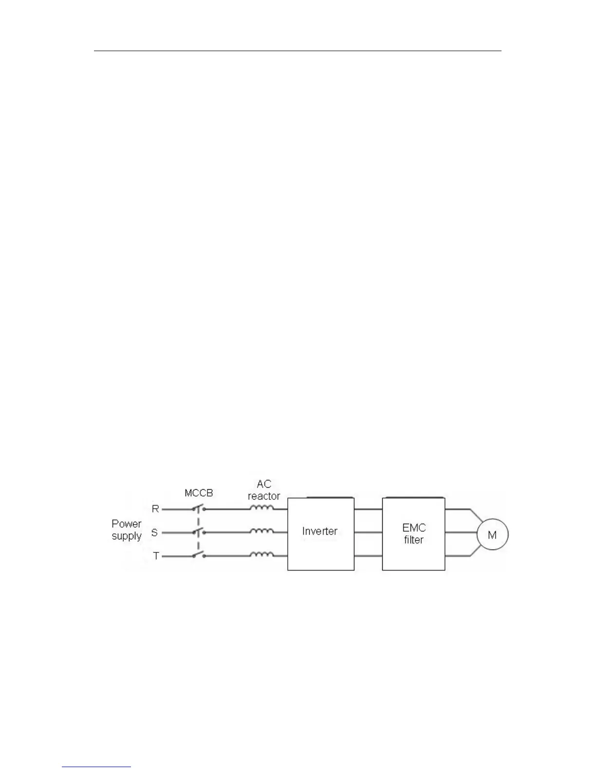
●4.4.3.2 Output EMC filter
EMC filter can minimize the radio noise cause by the cables between the inverter and
the motor and the leakage current of the conducting wires, which is illustrated as
below:
Figure 4.8 Wiring at motor side.
4.4.4 Wiring of regenerative unit
Regenerative unit is used for putting the electricity generated by braking of motor to
the grid. Compared with traditional 3 phase inverse parallel bridge type rectifier unit,
regenerative unit uses IGBT so that the total harmonic distortion (THD) is less than 4%.
Regenerative unit is widely used for centrifugal and hoisting equipment. Please refer to
The Manual of Regenerative Units of RBU Series for details.
 Loading...