CHV180 series frequency inverter special for elevator Wiring
.18.
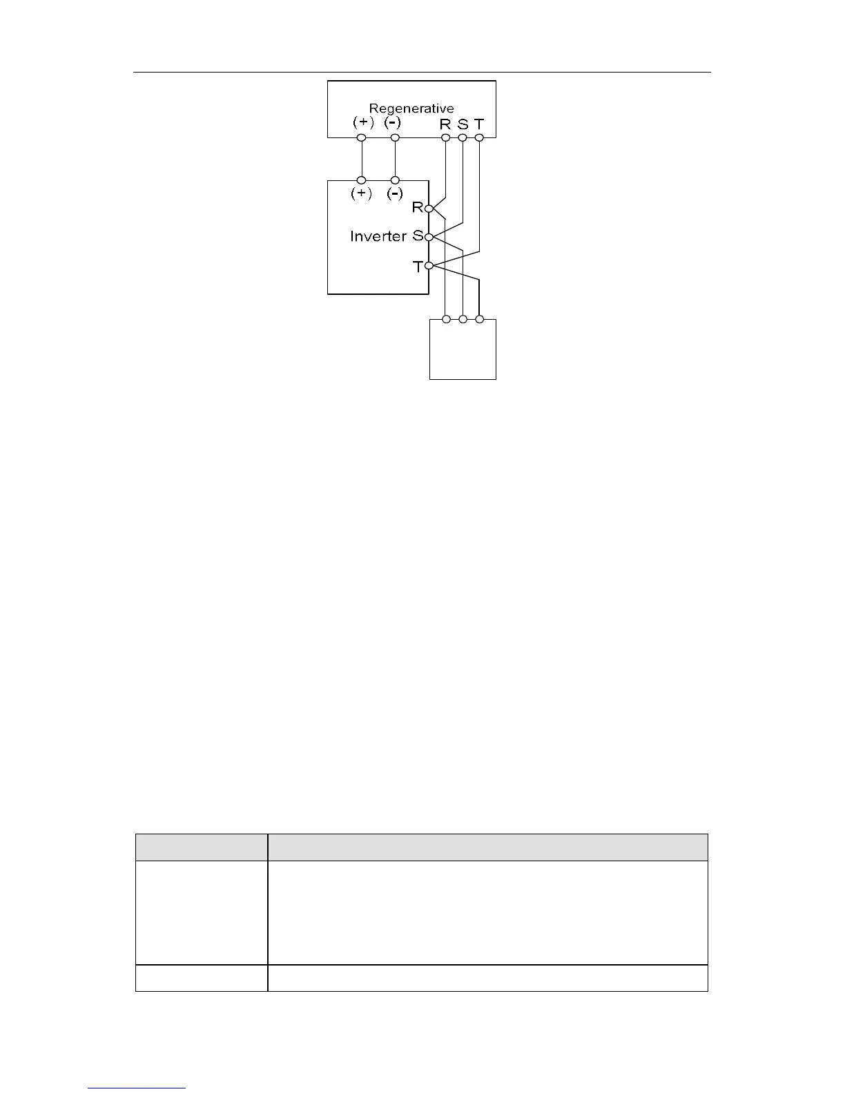
SR T
Grid
Figure 4.9 Wiring of regenerative unit.
4.4.5 Ground wiring (PE)
Ground the PE terminal of the inverter with grounding resistors (less than 10
) for the
insurance of safety and avoidance of electrical shock and fire. It is apporiate to use
thick and short multiple copper core wires whose sectional area is larger than 3.5m ㎡.
It is not recommended to use the public earth wire; otherwise, the grounding wires may
complete the circuit.
4.5 Wiring control circuit terminals
4.5.1 Precautions
Use shielded or twisted-pair cables to connect control terminals.
Connect the ground terminal (PE) with shield wire.
The cable connected to the control terminal should leave away from the main
circuit and heavy current circuits (including power supply cable, motor cable,
relay and contactor connecting cable) at least 20cm and parallel wiring should be
avoided. It is suggested to apply perpendicular wiring to prevent inverter
malfunction caused by external interference.
4.5.2 Control circuit terminals
Terminal Description
S1~S6
ON-OFF signal input, optical coupling isolation input terminal
with PW and COM.
Input voltage range: 9~30V
Input impedance: 3.3kΩ
PW External power supply. +24V terminal is connected to PW
 Loading...