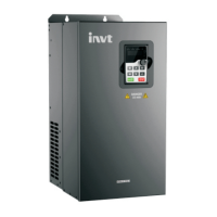
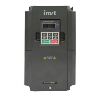
CHV180 series frequency inverter special for elevator Wiring
.19.
Terminal Description
terminal as default setting. If user need external power supply,
disconnect +24V terminal with PW terminal and connect PW
terminal with external power supply.
+24V
Provide output power supply of +24V.
Maximum output current: 150mA
COM
Common ground terminal for digital signal and +24V (or external
power supply).
AI1
Analog input, 0~10V
Input impedance: 10kΩ
AI2
Analog input, 0~10V/ 0~20mA, switched by J18.
Input impedance:10kΩ (voltage input) / 250Ω (current input)
GND
Common ground terminal of analog signal and +10V.
GND must isolated from COM.
Y1(Y2)
Open collector output terminal, the corresponding common
ground terminal is CME.
External voltage range: 0~24V
Output current range: 0~50mA
24V pull-up resistor range: 2kΩ~10kΩ
CME Common terminal of open collector output
+10V Supply +10V for inverter.
HDO
High speed pulse output terminal. The corresponding common
ground terminal is COM.
Output frequency range: 0~50 kHz
AO1(AO2)
Provide voltage or current output which can be switched by J19.
Output range: 0~10V/ 0~20mA
PE Ground Terminal.
RO1A, RO1B
and RO1C
RO1 relay output: RO1A—common; RO1B—NC; RO1C—NO.
Contact capacity: AC 250V/3A, DC 30V/1A.
RO2A, RO2B
and RO2C
RO2 relay output: RO2A—common; RO2B—NC; RO2C—NO.
Contact capacity: AC 250V/3A, DC 30V/1A.
RO3A, RO3B
and RO3C
RO3 relay output: RO3A—common; RO3B—NC; RO3C—NO.
Contact capacity: AC 250V/3A, DC 30V/1A.
4.5.3 Jumper on control board
 Loading...


