CHV180 series frequency inverter special for elevator Appendix C
.128.
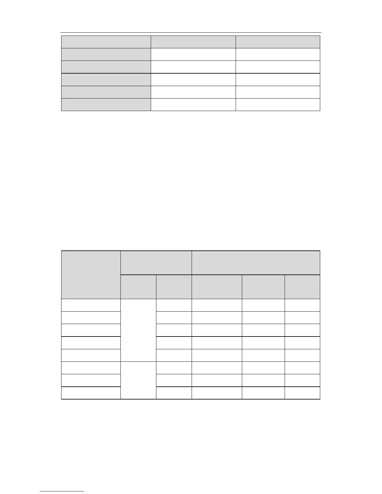
Inverter capacity (kW) Input filter model Output filter model
CHV180-011G-4 FLT-P04032L-B FLT-P04032L-B
CHV180-015G-4 FLT-P04045L-B FLT-P04045L-B
CHV180-018G-4 FLT-P04045L-B FLT-P04045L-B
CHV180-022G-4 FLT-P04065L-B FLT-P04065L-B
CHV180-030G-4 FLT-P04065L-B FLT-P04065L-B
C.2 Braking resistor/unit selection
C.2.1 Selection reference
When all the control devices driven by the inverter need quick braking, the braking
units need to consume the energy which is feedbacked to the DC bus. In CHV series
inverters, the inverters below 15kW (including 15kW) are embedded with braking units
and the inverters above 18.5kW (including 18.5kW) should select external braking
units. It is necessary to select proper braking resistor according to the inverter capacity.
In the application with 100% braking torque and 20% utilization rate of the braking unit,
the braking resistor and braking unit are shown as below. For the load which works in
the braking state for a long time, it is necessary to adjust the braking power according
to the braking torque and utilization rate of the braking. Counting at a long working time,
the power of the braking resistor is: p=(P8.07)
2
/R, R is the braking resistor
Capacity (kW)
Braking unit
Braking resistor (100% braking torque
and 20% usage rate)
Order No.
 Loading...